
Central Kitsap High School and Middle School Auditorium
The new Central Kitsap High School and Middle School campus was celebrated with a grand opening ceremony in October 2019. Located west of Seattle in Silverdale, Washington, the campus houses the new three-story, 325,000-square-foot building that combines and modernizes the community’s high school and middle school. The new structure sits at the center of the 52-acre site where the school will accommodate up to 2,100 students from grades 6 to 12 with two gymnasiums and an auditorium that both students and the community will use. The former middle and high school buildings were both located on the site and have been demolished to make room for the multiple playfields and parking lots.
Steel was the primary structural material utilized for the academic portion of the new facility, utilizing special moment frames for the lateral force-resisting system. Steel was also used for the gravity systems of the gymnasiums and auditorium but, in these spaces, special reinforced masonry shear walls were instead used for the lateral system. For all the masonry walls of the project, fully grouted 12-inch nominal concrete masonry units were specified.
The Auditorium
The 900-seat Auditorium is a central feature of the facility, centered between the high school and middle school wings of the campus. The audience faces a 48-foot-wide by 20-foot-high proscenium opening in a concrete masonry wall where musical and theatrical performances by students and community members will be given. There is an orchestra pit below the stage to provide space for live music with the shows at the school. Overhead catwalks and a 60-foot-high fly loft space provide for state-of-the-art lighting, sound, and prop equipment to be used.
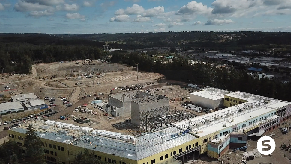
Aerial view of Central Kitsap High School and Middle School project during construction Courtesy of Skanska USA.
CMU was the chosen building material to span across the proscenium opening and provide support for the roof structure above rather than other traditional materials such as steel or precast concrete lintels. For this design feature, it was decided that CMU would provide the best aesthetic to the exposed wall and would reduce cost by eliminating the need for multiple trades to work simultaneously in the same area. With the auditorium roof framing into the CMU wall at an elevation of 42 feet, the depth of the beam that spans across the opening was designed for the full height between the top of the proscenium to framing, a 22-foot beam depth. The 24-inch-thick (nominal) by 13-foot-long support piers to each side of the beam provided the gravity support for the beam as well as the primary shear walls of the structure.
Design Parameters
Various dead and live loads were applied to the beam from the multiple building levels being supported, the theater rigging equipment installed inside of the fly loft, and the catwalks hung to the roof structure. Along with the self-weight dead load of the beam, an additional self-weight of 22 feet of CMU wall supported immediately above the beam was directly applied without the reduction that arching action would provide. Worst case loading conditions of uniform snow load or snow drifting at the multiple roof levels supported by the beam were also considered. In total, the ultimate load applied to the beam using load combinations from ASCE 7-10, Minimum Design Loads for Buildings and Other Structures, was calculated to be about 13.0 kips/ft.
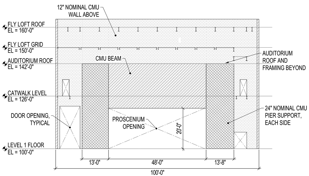
Labeled elevation of the CMU wall and beam.
With the beam parameters set at 22-feet-deep by 12-inch-thick (nominal) and 48 feet long, TMS 402, Building Code Requirements for Masonry Structures, was followed to determine the design approach to the beam. After calculating the effective length of the beam, an effective span-to-depth ratio, leff/dv, of approximately 2.5 was determined. The code put the flexural design into the deep beam code section when fixed-end boundary conditions were applied, or to standard beam design when viewed as a simple span beam. Flexural reinforcement was designed for each case, but TMS 402, Section 5.2.2.3, required that the flexural reinforcement be detailed such that the reinforcement was distributed in the tension zones of the beam equal to half of the beam depth.
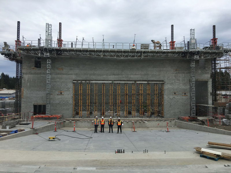
Elevation of the CMS wall and beam during construction. Approximately 40 feet of 60 feet completed.
Although the required beam flexural reinforcement was determined, it was not the controlling factor for the longitudinal reinforcement; the out-of-plane load case would control. A vertical two-span condition from the top of the proscenium opening to the top of the fly loft roof, with mid support at the auditorium roof, was used to more accurately analyze the internal forces of the wall and beam. An equivalent spring reaction was placed at the top of the proscenium opening, with the stiffness of the spring calculated from the stiffness of the horizontal span of the bottom 11 feet of the beam between the support piers.
By using this method, the out-of-plane force against the wall at the critical location at the bottom of the beam was reduced from 60 psf to 50 psf. Fixed-end boundary conditions with the 48-foot span between supports were then used to design the reinforcement required for the out-of-plane flexure. With consideration of the in-plane strength, in-plane detailing, and out-of-plane strength requirements, the final design for the longitudinal reinforcing bars was U.S. #5 size at 8-inches on-center for the beam depth.
Shear design of the beam closely followed the procedure laid out in TMS 402, Section 9.3.4.1.2. The nominal shear capacity of the beam from the contributions of masonry shear strength and supplemental shear reinforcement was compared to the code maximum based on the beam’s shear-span ratio, Mu/(Vudv). U.S. #5 reinforcing bars at 8 inches on-center along the beam were also used for the shear reinforcement of the beam. The beam’s shear design resulted in a demand-capacity ratio of approximately 0.50, with the code-maximum shear capacity values as the controlling capacity.
The TMS paper, The Size Effect in Reinforced Masonry, by S. Sarhat and E. Sherwood, was studied to determine how the size effect phenomena of a deep beam could affect the load-carrying capacity of the beam. As the effective beam depth increases, cracks along the tension face of the beam increase in width and spacing. This causes shear failure of the masonry at lower shear stresses due to reduced mechanical interlocking of the aggregate. It was discussed between engineering team members that, due to the amount of longitudinal reinforcement and shear reinforcement along the length of the beam, longitudinal cracks located in the tension face would be kept relatively small and would not impact the shear strength of the beam. Therefore, the size effect would be negligible.
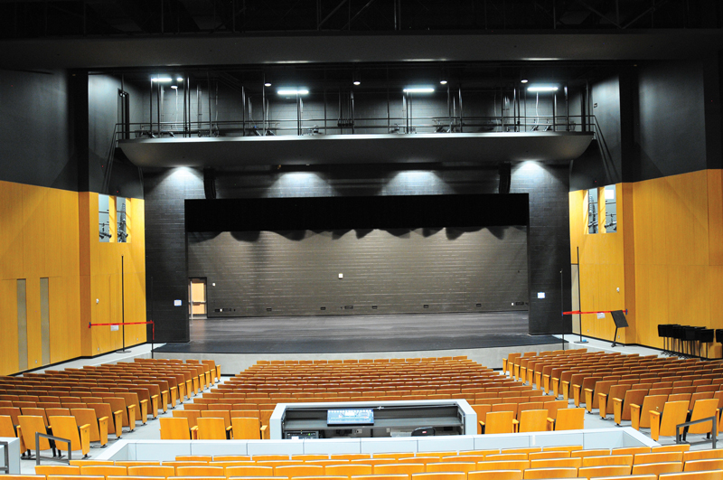
Finished interior view of the auditorium and CMU wall.
Construction Challenges
The primary challenge for the contractor in constructing this large beam was providing adequate support while the masons were laying the blocks. With the orchestra pit located directly below the proscenium, an engineer working with the mason subcontractor designed a two-level shoring system. Although the shoring was removed before the erection of the steel began, it was designed to hold the full self-weight of the beam, CMU wall above the beam, and steel roof framing. This gave the general contractor flexibility on the removal date once the wall’s grout strengthened. Grout lifts of 5 feet 4 inches were used to minimize the number of lifts that were required to be poured.
Creative Beam Design
The Central Kitsap High School and Middle School Replacement project was an extensive campus overhaul that brought the two schools into a single facility and provided amenities that would be accessible to the community. The facility’s feature of the auditorium and the architect’s desire to maintain the same material along the wall allowed CMU to be utilized to span across large openings rather than other traditional building materials. The 48-foot-long CMU beam was a unique design challenge for the engineering team, demanding creative thinking and pushing the boundaries of beam design.■
References
Sarhat, S. R., and Sherwood, E. G. (2015). “The Size Effect in Reinforced Masonry,” 12th North American Masonry Conference, Denver, CO.
TMS 402/ACI 530 (2013). Building Code Requirements and Specifications for Masonry Structures, The Masonry Society (TMS), Longmont, CO.