
More than 100 years after its original construction in 1912, the First National State Bank Building in Newark, New Jersey (Figure 1) is ready to return to prominence. Located near the intersection of Broad and Market Streets, one of America’s busiest intersections just after the turn of this century, the rehabilitation of this structure is paramount to the ongoing revitalization of Newark’s historic commercial and business district known as the “Four Corners”. The structure consists of a 12-story mid-rise building with concrete slabs, steel I-beams and built-up steel columns; an adjacent three-story addition with concrete slabs and steel W-shape beams and columns constructed at an unknown date; and a more recent four-story structural steel, masonry block and brick stair and elevator tower at the very rear of the property.
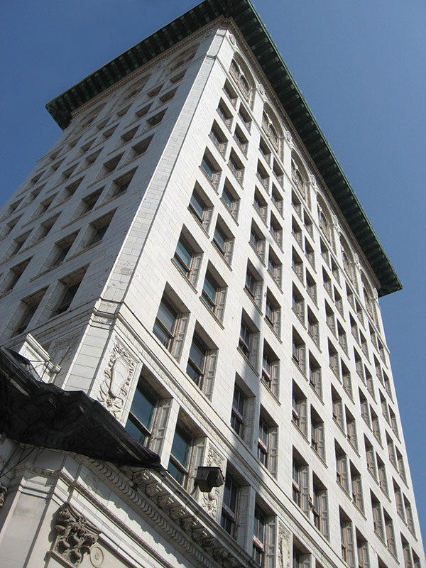
Figure 1: Existing façade prior to renovations.
The facility was originally designed as a bank and office building; however, in recent years most of the upper floors remained vacant while the ground floor was used occasionally by retail and office tenants. The developer engaged Pennoni Associates Inc (Pennoni) to perform the structural engineering services required to transform the building into a mixed-use facility consisting of a hotel with restaurant, dining, and retail spaces. These services included designing a two-story overbuild above the existing three-story addition, designing a nine-story stair and elevator addition at the rear or east side of the footprint of the existing 12-story structure, strengthening the existing roof structure above the 12th story to support an occupied terrace, and several other structural modifications required to complete the overall adaptive reuse.
Designed by prominent American architect Cass Gilbert, whose other works include the Woolworth Building in New York City and the United States Supreme Court Building in Washington, D.C., the First National State Bank Building is a classic example of “skeleton” construction, for which Gilbert was one of the earliest pioneers. Skeleton construction consists of a primary steel frame directly supporting exterior brick walls as a non-load-bearing cladding system. This method of construction formed the basis for modern high-rise construction methods still employed by engineers and architects today, and served as an advancement of the “cage” method of construction. Cage construction involved steel frames supported by steel columns with thickened exterior brick walls that supported their own self-weight, similar to the previous method of using exterior brick walls to support the adjacent floor framing.
In order to support the exterior brick cladding on the steel frame, the structure of the First National State Bank Building utilized a double spandrel beam in which the interior member supported the adjacent floor framing and a small portion of the exterior brick cladding, while the exterior member supported only the exterior brick cladding (Figure 2). Both spandrel beams framed to, and were supported by, the same steel column, but the exterior member required an extended single plate shear connection because it did not align with the column centerline.
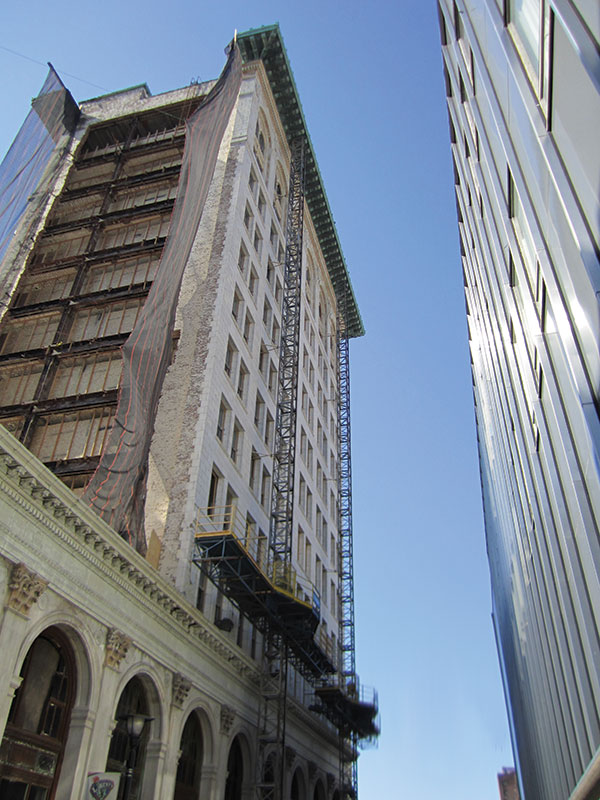
Figure 2: Exposed existing spandrels after east masonry wall demo.
Due to the historical significance of many of the structures designed by Cass Gilbert, structural drawings of many of his buildings, including the First National State Bank Building, have been preserved by the New York Historical Society as well as the Library of Congress. In addition, the original mid-rise structure and the adjacent low-rise addition were added to the National Register of Historic Places in 1977. The structural drawings were prepared on linen sheets, and due to their age and fragility, the New York Historical Society would not allow the drawings to be removed from their office for reproduction purposes. Therefore, each drawing sheet was laid out on a table at the Historical Society’s office and photographed for future use in analyzing the existing structure for the required modifications. The first step was taking a photograph of an overall drawing, followed by taking close-up photographs of portions of the same drawing that could be laced together in sequential order so that the entire drawing could be viewed in greater detail at Pennoni’s Philadelphia office (Figures 3 and 4). This process was repeated until the entire set of original drawings, including all notes, schedules, and details, were photographed.
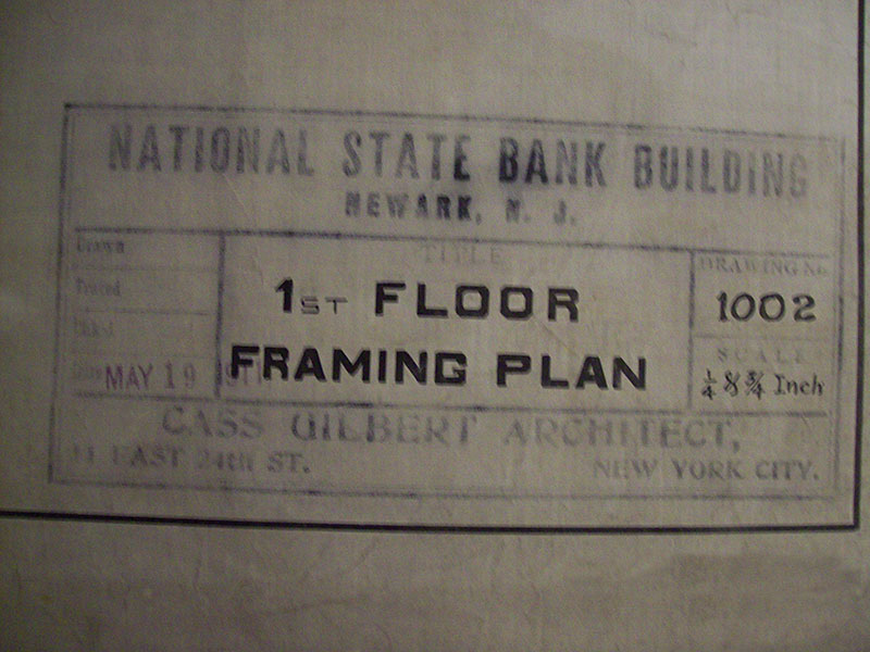
Figure 3: Cass Gilbert drawing titleblock.
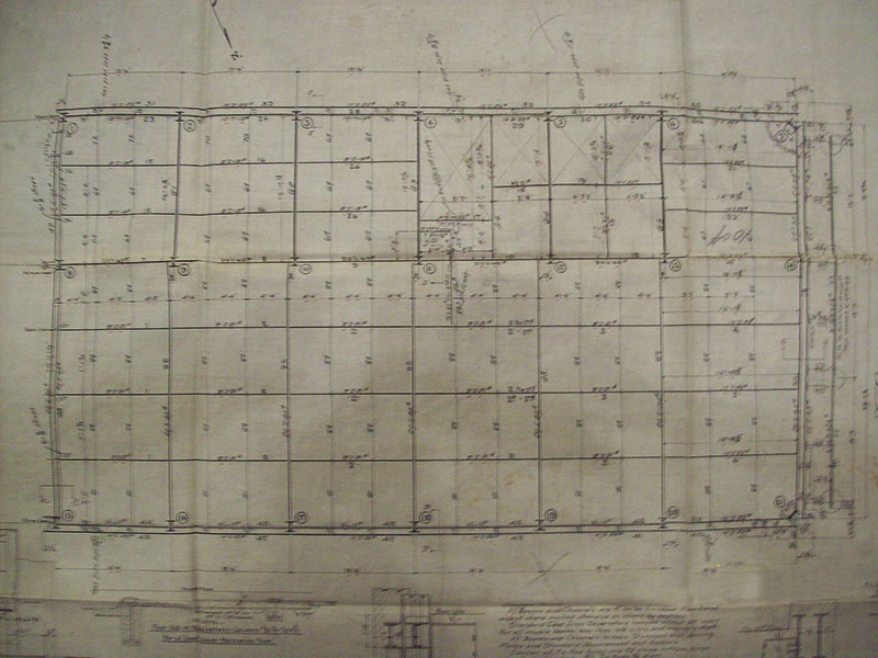
Figure 4: Cass Gilbert drawing first floor framing.
A review of the drawings revealed that the second floor of the mid-rise building was originally constructed as a mezzanine area overlooking the first floor lobby below. However, at some time during the life of the building the remaining portion of the second floor was infilled with steel and concrete framing similar to the original structure. Existing drawings for the infill framing were not available.
Extensive field investigations were still necessary in order to supplement missing information on the structural drawings, and to confirm that the members shown on the drawings were actually in place. Structural drawings were not available for the low-rise addition, so more extensive field investigations were required in order to determine the structural members for this portion of the building. In both portions, steel beams were encased in concrete and steel columns were encased in hollow clay tile blocks, a common method of providing fire protection during the early 20th century (Figure 5). The concrete and clay tile encasements were removed from a portion of the beams and columns in order to perform the field investigations.
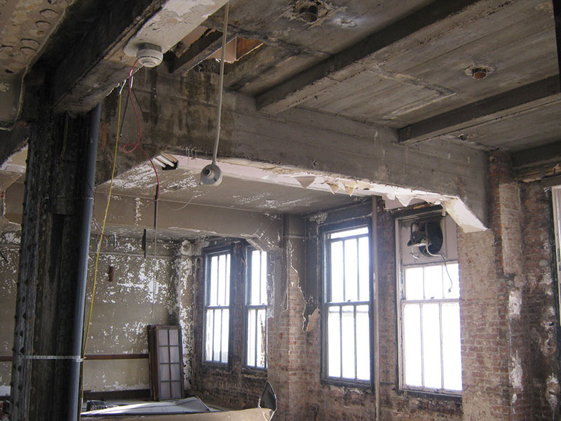
Figure 5: Existing encased bent prior to renovations.
Physical properties of selected steel beams and columns were measured, then compared to the physical properties of steel beams and columns in two AISC published databases for historic shapes and specifications in order to verify that the members shown on the existing structural drawings were in fact used in the actual construction. AISC databases were also used in order to establish the yield strength of the steel at the time of fabrication; however, steel coupons were also taken from beams at various locations in both the mid-rise and the low-rise buildings in order to determine the chemical and material properties of the steel, including weldability and actual yield strength. Finally, concrete cores were taken in several locations in order to verify the thickness, unit weight, and compressive strength of the slabs. Locations chosen for the concrete cores included the roof of the mid-rise and low-rise buildings in order to determine if topping slabs were present to provide drainage, and at the typical floor in both the mid-rise and low-rise buildings to determine the slab construction. The results of the field investigations, in conjunction with available structural drawings, were used to determine the structural capacity of the existing building.
The renovation of the low-rise building called for a two-story addition consisting of hotel rooms and a rooftop terrace. The first challenge encountered was the need to recess the north face of the vertical extension from the existing north elevation of the original facility because of a National Register of Historic Places and State Historic Preservation Office (SHPO) requirement not to alter the sightlines of the building as viewed from Broad Street. As a result, the north exterior wall of the new addition was set back from the north exterior wall of the existing low-rise below. The existing interior and exterior columns along the south exterior wall were used to support the new addition, but a large cantilever at the new fourth and fifth floors was required to support the portion of the addition on the north side of the interior column line (Figure 6). Excessive deflections at the cantilever were mitigated by using an upward camber equal to the total dead load deflection, and by providing slightly deeper members than those required for strength design only.
Figure 6: 4th & 5th floor addition north elevation cantilevers.
A second challenge encountered with the design of the 2-story addition was determining the capacity of the existing columns and foundations that would be required to support two new floors. Using the physical column properties measured during the field investigations and the mechanical properties established via the steel coupon testing, the columns were determined to have significant reserve capacity based on their unbraced lengths and the loads applied by the three existing framed floors. In fact, it was determined that the low-rise building had been designed for a full 12 stories to match the high-rise tower, but the construction had stopped at the third floor, which then served as a roof over the second floor. This conclusion was confirmed during demolition of the clay tile providing fire protection around the low-rise columns and further investigation of the existing topping slab on the low-rise roof. At these locations, the existing columns were found to have bolt holes in their webs and flanges to accept splice plates for future columns above.
Part 2 of this article will appear in a future issue and will discuss renovations associated with life safety improvements and enhancements to the space utilization of the 12th floor and roof.▪