
Part 2
On August 24, 2014, the South Napa Earthquake left the Napa County Historic Courthouse heavily damaged with partially collapsed walls, ceilings, and extensive wall cracking (Figure 1). The City of Napa red-tagged the courthouse as un-occupiable, which began the extensive damage documentation effort outlined in the December 2019 edition of STRUCTURE. After documenting and assessing damage, the design team refocused efforts towards a solution to repair and preserve as much of the historic building as practical while providing improved detailing.
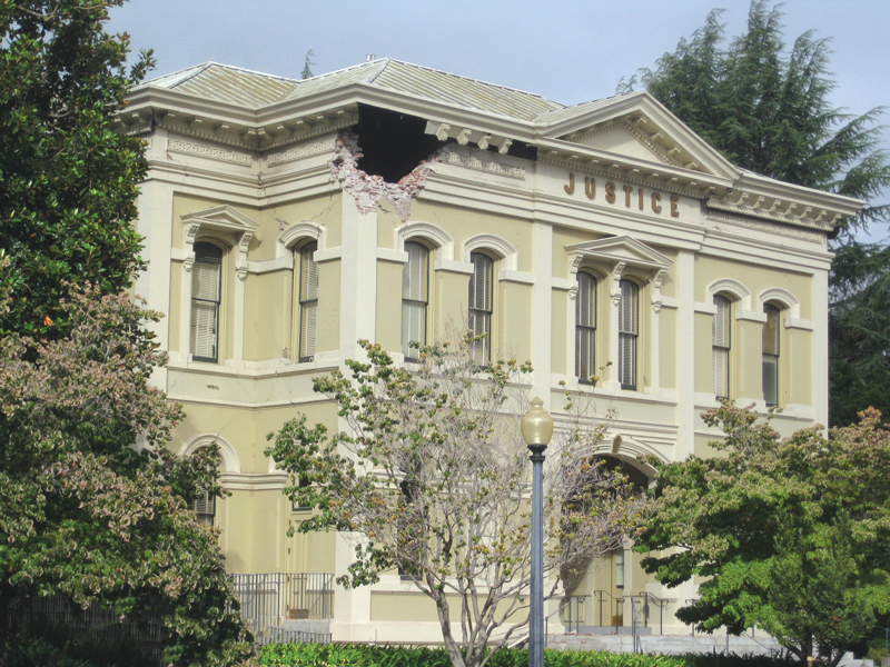
Figure 1. Entry showing damage taken the morning of the earthquake.
Construction Documents
The 140-year-old building is constructed with unreinforced brick, an “archaic” structural system. After considering the California Building Code (CBC) or American Society of Civil Engineers Standard for Seismic Evaluation and Retrofit of Existing Buildings (ASCE 41), ZFA Structural Engineers decided the California Historic Building Code (CHBC) was the appropriate design code for the project because it would allow reuse of the historic brick walls.
Repair Approach
An overarching goal of the repair was to save the historic brick structure in its original state utilizing the original construction, where possible, and providing modern construction techniques with ductile detailing where rebuilding or strengthening the damaged condition was required. Because of the historical materials and construction techniques, 140 years of use and modification, and the wide range of damage throughout, a single repair option was not appropriate. Repair details were approached with continuity, resilient detailing, and construction tolerances in mind. During documentation, the high level of historic brick masonry craftsmanship became apparent, particularly at the exterior of the building (Figure 2). Therefore, repair work was kept on the inside face of the building to preserve hand-shaped decorative brick features and trim adorning the exterior of the structure. In areas of new wall construction, these features were recreated with modern appendages and plaster to preserve the historic appearance. Additionally, the historic interior wood trim and wall wainscot were salvaged and reinstalled throughout the building.
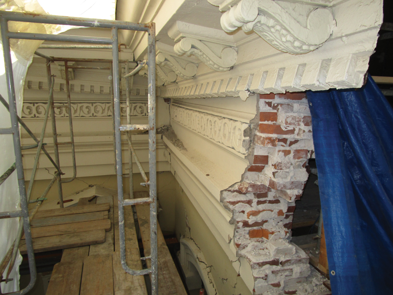
Figure 2. Historic exterior wall brick construction and dental cornice.
Traditional Repair Methodology
Traditional repair methods, such as repointing mortar beds and grout injecting cracks, were used where observed damage was less extensive and cracking was limited to discrete locations. This was primarily concentrated on the first floor and the west end of the second floor that experienced smaller deformations.
Grout injecting was determined to be preferable for the repair of distinct larger cracks, but an alternative repair solution was needed in areas of numerous cracks prevalent throughout the second floor.
Fabric Reinforced Cementitious Matrix Overlay
Early in the repair design, the design team considered using traditional Fiber Reinforced Polymer (FRP) overlay on brick walls demonstrating extensive cracking. Due to surface preparation requirements and material incompatibilities of FRP (epoxy resin vs clay and mortar), the team turned to a new overlay product uniquely suited for brick masonry construction called Fabric Reinforced Cementitious Matrix (FRCM) used extensively in Europe. FRCM was used to repair brick masonry walls with significant cracking but minimal permanent deformations, and to provide continuity through floors, walls, and around corners. As a new product being brought to the United States by manufacturers, including Simpson Strong-Tie, FRCM presented several challenges and opportunities from design through construction. These will be discussed in a future Part 3 article in STRUCTURE.
CMU Design
Reinforced CMU construction was used in place of brick to reconstruct areas where significant damage and permanent seismic deformations required walls to be rebuilt. These areas were primarily concentrated at the east end of the second floor. Special design consideration was taken to avoid concentrating lateral and overturning loads from relatively stiff new CMU above to the remaining historic brick below. Analytical models were created using tested in-situ historic brick material properties to determine approximate stiffnesses of existing wall piers to be replaced. The same piers were then modeled with multiple CMU construction options, including partially grouted CMU, adjusted specified compression strength of masonry (f´m) using different grout, different block and mortar properties, and alternate block layouts to compare stiffnesses and strengths.
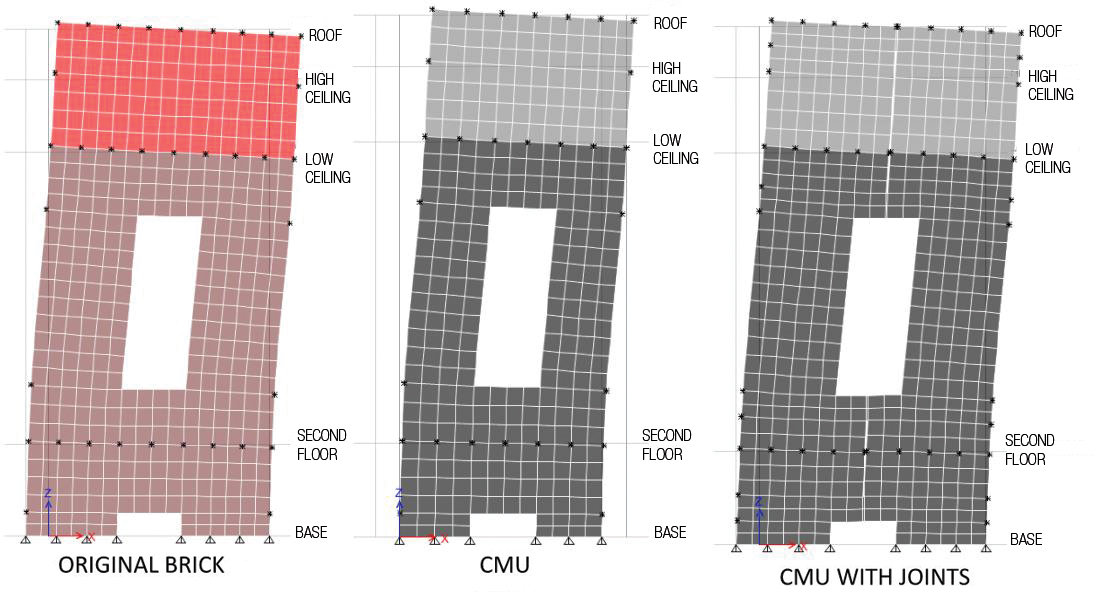
Figure 3. Analysis model showing original brick, CMU, and CMU with control joints.
These adjustments did not provide the desired reduction in stiffness; therefore, strategically located control joints were added to further reduce the stiffness of the areas rebuilt with CMU (Figure 3). The final design included a stacked bond, in lieu of a traditional running bond and control joints located above and below windows, at reentrant corners, and regular vertical spacings in long rebuilt walls. The final layup more closely matched the stiffness of the original brick walls such that new walls work in unison with existing walls, and lateral loads are not concentrated in any one area. Additionally, many of the exterior reentrant corners, whose stiffness concentrated seismic load and deformations, were reconstructed out of CMU with control joints in the corners to decouple perpendicular walls.
Combining the CMU rebuild with existing historic brick construction presented dimensional obstacles that were addressed in detailing. The brick arches at the 1st and 2nd-floor windows of rebuilt walls were recreated with precast concrete elements to adjoin rectangular CMU with curved historic windows. CMU was aligned at the exterior face of brick to minimize furring and plasterwork on the visible historic exterior and aid in providing a flush plaster joint with the existing plaster finish. At interior walls, CMU was detailed to be centered on the brick below to limit the dimensional offset from the brick below each side for installation of FRCM continuity laps. Transitions of CMU to unreinforced brick were dowelled with alternating embedment lengths to tie the walls together and avoid creating a defined weak plane in the brick similar to those observed at the 2003 concrete shear wall interface.
The unique condition of anchoring new CMU walls to existing in-place ceiling framing allowed for cast-in-place anchorage to be located accurately, avoiding the traditional difficulties associated with locating cast-in-place anchorage. Connections employed slotted holes, post-installed anchorage, acceptable dimensional ranges, shims, and acceptable offsets to allow for as much existing variability as possible, maximizing construction tolerances.
Construction
As is typical for working within an existing building, multiple unforeseen conditions were discovered during construction. This included uncovering additional damage to brick walls, unknown wall voids or changes in wall thickness, minor areas of dry rot, and incomplete or changed configuration of work shown in the 1977 retrofit documents.
Damage documentation was largely completed by observing cracking in the finished plaster to assess overall damage before requiring expensive removal and reapplication of plaster. Localized areas were selected for removal to verify that plaster cracking correlated to a crack in the brick substrate. Removing plaster during construction often revealed that numerous small patterned cracks observed in the plaster typically resulted from fewer large cracks in the brick ultimately requiring grout injection. Even in areas receiving FRCM overlay, larger, open cracks were grout injected to provide a cohesive substrate for the FRCM. The process of injection uncovered a handful of unforeseen wall voids and chases that required grout filling before crack injection.
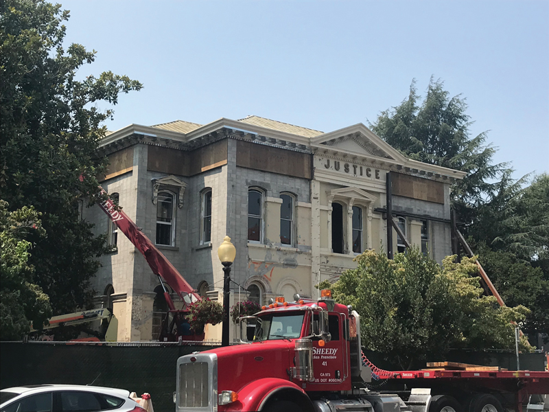
Figure 4. CMU reconstruction of damaged 2nd-floor walls.
In addition to material similarities, CMU was used in the project for its adjustability to accommodate small dimensional variations in the existing structure. Modern construction procedures and metrics focus on installing materials straight, true, and plumb rather than matching existing conditions. The roof and second floor experienced small permanent displacements, which were compounded with plan dimension variations along the length and height of each wall. This created a challenge in rebuilding a new “straight” wall between two existing points (Figure 4) while still supporting the floor and ceiling. This condition was resolved through shimming of ledgers at small gaps and providing bearing angles at larger offsets.
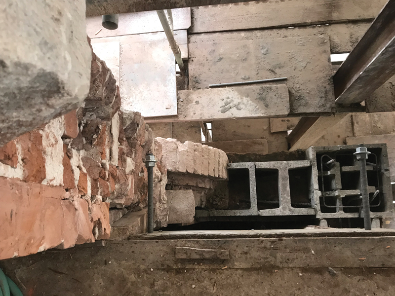
Figure 5. Detail of CMU interface with historic brick arch.
While CMU has some adjustability to accommodate small existing dimensional offsets, the number of intricate interface conditions to existing construction was a challenge. CMU had to interface with historic brick arches (Figure 5), existing floors and ceilings, adjacent precast concrete lintels (Figure 6), uneven base levels, wall anchorage, and existing penetrations while adjusting to match existing walls. The result was a number of details, both planned and unforeseen, requiring a level of mason care and ability beyond that of typical construction.
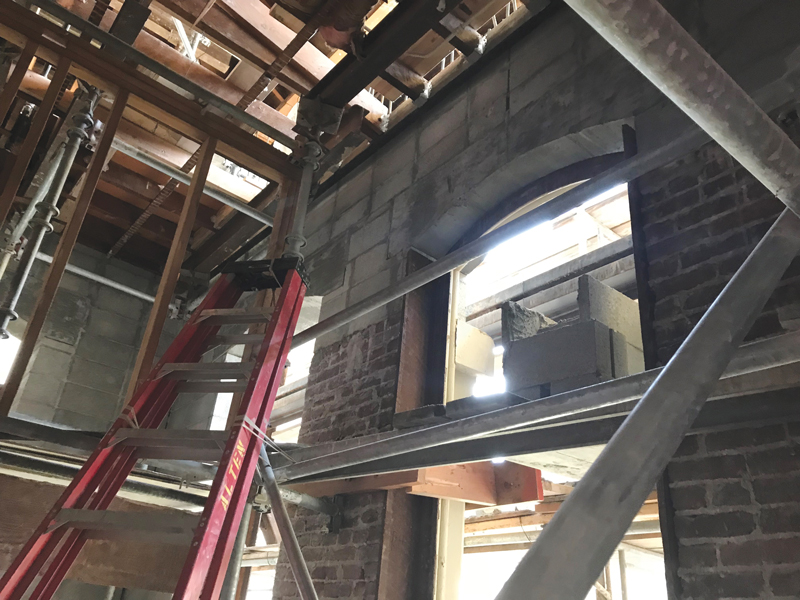
Figure 6. CMU and precast lintel construction above the original brick wall.
Conclusions
From the beginning of the damage documentation phase in early 2016 to completion of construction, the overarching goal was to preserve the historic fabric of the building while providing improved resiliency, with modern structural design and detailing techniques woven into the project.
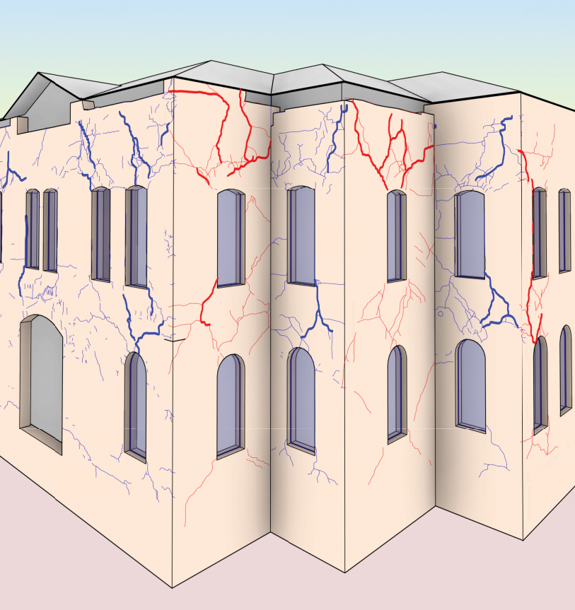
Figure 7. Example of damage documentation drawings.
Due to the archaic materials, the age of the building, and the architectural layout of rooms, the extent of damage from a brief walkthrough could be easily underestimated. Extensive documentation utilizing new technologies and proven methods to create a 3-D BIM model, clearly and effectively documenting the as-built/damaged building, allowed all stakeholders to witness the entire building as affected by the earthquake (Figure 7). While time-consuming, this detailed process was critical to the success of the project in supporting a step-by-step agreement process in the scope of work and extent of repairs with all stakeholders.
A combination of repair strategies was used, including repointing, grout injection, localized rebuild of brick, FRCM overlay, and reconstruction of walls with CMU. Reconstructed CMU walls provided at areas of permanent deformations were designed and detailed to perform similarly to the original construction, allowing the first floor walls to remain with minimal alterations. Additionally, the CMU thicknesses closely matched the original building configuration, maintaining the architectural layout and maximizing reuse of historic trim and wainscot.
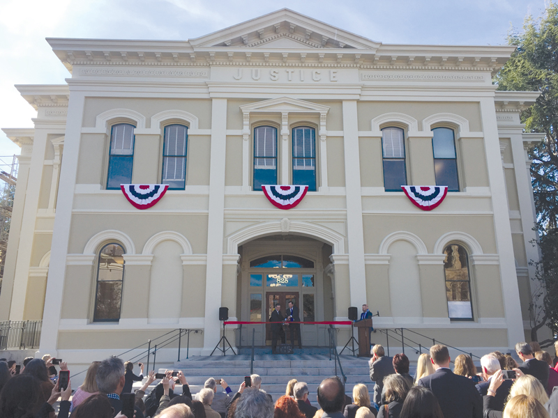
Figure 8. Grand opening on January 22, 2019.
While there were challenges and unforeseen conditions along the way, the building has successfully reopened and provides the County with services in a uniquely rich environment (Figure 8).
The design, construction, and lessons learned of the Fabric Reinforced Cementitious Matrix overlay system will be covered in a future STRUCTURE article.■