
Multi-Unit Residential Construction
Pre-fabricated, structural cold-formed metal framing (CFMF) bearing walls are a trending construction system and an economical alternative to structural steel or reinforced concrete systems for mid-rise construction. CFMF wall systems are particularly desirable for 6- to 12-story multi-family apartments or condominiums, student housing, senior living, and hotels. Vertically-aligned residential demising and partition walls allow the CFMF to stack like timber-framed or concrete masonry unit (CMU) bearing wall construction. However, CFMF wall buildings are less height restrictive than timber due to steel’s higher strength and not as labor-intensive as CMU because of pre-fabrication. Additionally, CFMF systems integrate wall panels as the structural system in what would typically be non-structural, stick-built partition walls.
The prevalence of CFMF wall panel systems comes with design and construction challenges. Delegated design integration, trade coordination in a traditionally non-structural element, and fire-resistive detailing are among the challenges for this system. This article summarizes the CFMF system layout process, design and specification options, and considerations that may be overlooked in initial planning and pricing.
System Overview
CFMF systems are most efficient when the wall panels align, or “stack,” from foundation to roof. Multi-unit residential construction often integrates programming space for retail, office, amenities, or parking typically at the lowest levels of the building. In these cases, the CFMF bearing walls are constructed on a podium level, typically of structural steel or cast-in-place reinforced concrete. Both systems can be engineered to support discontinuous bearing walls and to provide heightened fire rating separation that may be required between differing occupancies. From the onset of a project, there should be a dialog between the design team and the owner to stack the walls, and ideally the wall openings, to minimize transfers within the CFMF system.
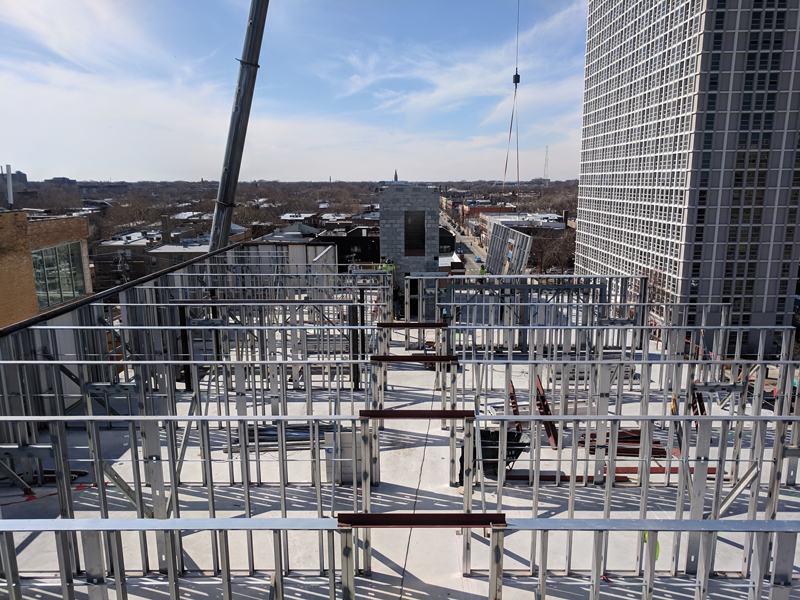
Pre-fabricated, structural CFMF wall panels. Courtesy of Bear Construction Co.
CFMF bearing walls can be spaced between 10 and 32 feet apart depending on the span capabilities of the floor construction. To span between the bearing walls, floor system options include cast-in-place concrete on unshored composite steel deck, cast-in-place concrete on shored long-span steel deck, or precast, prestressed hollow-core planks. Alternatively, floor construction may consist of concrete panels or steel deck supported on CFMF floor joists that span between the bearing walls.
Each floor system has advantages and disadvantages. For example, concrete on unshored composite steel deck requires less labor associated with shoring than shored long-span steel deck; however, unshored steel deck is typically limited to a span length of about 15 feet, where long span deck can achieve up to 32 feet between structural walls. Precast, prestressed hollow-core planks can achieve similar spans to long-span steel deck; however, planks may require a structural topping for floor levelness and are a heavier system resulting in increased load on the wall panels, podium, and foundations.
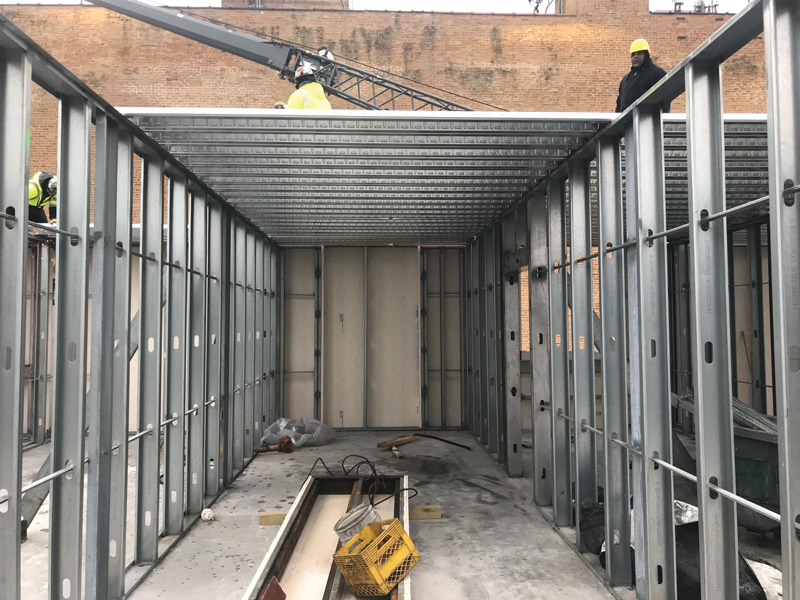
Unshored composite steel deck construction.
Compared to steel deck options, CFMF floor joists may be appealing because of their span capabilities without the use of shoring; however, a CFMF floor joist system is generally 6 to 12 inches deeper than a steel deck system leaving less room for MEP distribution, requiring lower ceilings or necessitating taller floor-to-floor heights. Additionally, CFMF floor joist systems may require a fire-rated ceiling assembly where steel deck systems can typically achieve an unprotected fire-rating within the concrete. Steel deck options (shored or unshored) are appealing, given their simplicity in detailing and thin profile. For both decking and CFMF joist systems, if the span is parallel to a central corridor, a header is required to span from the end of the CFMF wall panel over the corridor. The header is a part of the structural load path and may require a 1- or 2-hour fire rating.
The lateral load resisting system (LLRS) for a CFMF building can be of a variety of structural systems. It may be beneficial to utilize the CFMF walls as the lateral system, relying on either sheeting or CFMF steel straps. In this case, the transfer of overturning moments in the wall systems and transfer of the loads from the CFMF walls to the podium structure are important considerations; in the case of the former, the additional details may detract from the efficiency of the system. Alternatively, walls around the stairs and elevators are an opportune location to introduce reinforced concrete shear walls, CMU shear walls, or steel braced frames for the LLRS. Regardless of the system chosen, the sequence of trades is a critical discussion to have with prospective contractors, whether they are involved early in the project in a design-assist role or bidding the project.
Design and Specification
Traditionally, CFMF wall panel construction has been governed by systems that were developed by fabricators and their Specialty Structural Engineer (SSE). The SSE designs these systems, which are tuned to the preferred fabrication and installation techniques of the contractor. An alternate approach is for the Structural Engineer of Record (SER) on the design team to design a custom stud framing system or to delegate the design of a custom system to the contractor. The SER designing the system is the least common approach and is not discussed here.
An appropriate delegated design, whether for a custom or proprietary system, requires the design team to identify the location and extent of the load-bearing CFMF walls on the drawings. The delegated design of a building system describes a scenario where the SER provides a set of design criteria for a contractor’s SSE to follow to design, fabricate, and install the identified building system. In addition to identifying the CFMF wall location and extent, it is essential that the design team indicate other trades, both structural and non-structural, that interface or are integral to the CFMF walls.
A crucial part of delegated design criteria is the communication of wall and floor loading information to the contractor’s SSE. Floor load plans should be employed to show the magnitude and extent of superimposed dead and live loads, particularly large or non-uniform loads and exterior wall loads. Specific details may also be required to indicate the location and magnitude of exterior wall loads or point loads, such as transfers, corridor transfer beams, and rooftop equipment.
Exterior wall cladding is frequently a partial or complete delegated design. The intersection of multiple delegated design components can result in poor coordination during construction. The design team needs to clearly document basis-of-design details for the integration of the various systems as a basis for contractor bidding. In addition, a responsibility matrix is a useful tool to document the roles of the Architect of Record (AoR), SER, the General Contractor (GC), the specialty subcontractors, the CFMF fabricator/installer and their SSE, and the exterior wall fabricator/installer and their SSE during the submittal review process and the subsequent construction. The matrix can be published with the construction documents to define the design demarcation for each structural engineer. The design team can rely on the matrix during submittal reviews to indicate necessary coordination with other trades.
Regardless of the system – proprietary or custom – the SER should develop a preliminary analysis of the typical CFMF wall components both to establish the acceptability for the intended layout and to provide a basis of design for pre-construction budgeting and bidding. This effort validates the approach, establishes design loads for the podium and foundations, helps the SER identify key layout options or constrictions, and indicates to the SER where special detailing, minimum size, or material gauge are required. This will help the SER develop a more reliable delegated design.
Design and Construction Considerations
Podium Construction
Podium level construction should be designed to heightened deflection criteria to account for the sensitivity of the gypsum wallboard (GWB) clad CFMF bearing walls. Accumulated displacement can result in non-structural finish cracking if a podium level is not sufficiently stiff. Early programming should consider the increased depth of the structure below the first floor of CFMF bearing walls.
Fire Ratings
As the primary structural load carrying members, CFMF may be required to achieve up to a 2-hour fire rating. A 2-hour rating is achieved with a second layer of GWB on each side of the wall. This is an additional weight that needs to be considered in the design of the studs and clearly indicated in the delegation language to the SSE. An additional consideration for architects and contractors is the continuity of the rating – it must continue around door jambs, electrical boxes, and similar items integral with the structural CFMF wall. To the extent possible, the design team should coordinate all penetrations into a CFMF wall to occur within a non-structural portion of a CFMF structural wall to simplify the fire rating details during construction.
Future Flexibility
While CFMF allows a typically non-structural partition wall to serve as a primary structural element, it does not typically allow for future flexibility. While this may be acceptable for hotels and dormitories, it may be less desirable in apartments and particularly condominiums where owners may want the opportunity to modify their unit or combine units in the future. A hedge against limiting future flexibility is to use a long-span floor system wherein either the exterior and corridor walls are the primary bearing walls, or only unit party walls are the primary bearing walls, or a combination thereof.
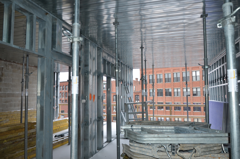
Shored long-span steel deck construction.
Non-Stacked Walls
CFMF bearing walls are an efficient system for repetitive usage programs such as residential. However, when atypical programs migrate into, under, or above CFMF bearing walls, inefficiencies encumber the system. This typically takes the form of hot-rolled structural steel within the steel stud walls, an independent structural steel frame, or similar programs. This results in inefficiencies in the CFMF wall design and fabrication and increases the complexity of construction trade sequencing.
Top Track Details
Top tracks within a CFMF bearing wall function as a load-distribution element where the floor system (e.g., the low flute of steel deck or the flange of a CFMF joist) does not necessarily align with a vertical stud. Wall panels are typically installed on top of each floor level, so the top track should be designed/detailed to transfer the load of the floor system and upper-level floors to the adjacent vertical stud. In the authors’ experience, it is a false economy for the contractor to take a cost savings by presuming the installers will align the floor system with individual studs.
Construction Sequencing
Forethought into the coordination of trades during the vertical erection sequence will drive construction efficiency. Traditional trades such as masons, carpenters, ironworkers, concrete suppliers, and concrete placement workers will need to be staged as each floor is constructed, and they will need to be educated about the integration of their systems with CFMF construction.
Structural Studs vs. Partition Studs
Historically, CFMF is not part of the primary structural building frame, typically serving as an exterior backup wall or a partition wall. While this is part of the intrigue and efficiency of the system, it can create confusion on the construction site. Clearly documenting the structural CFMF in both the structural and architectural drawings is important. It is more important, however, to educate the contractor and their subcontractor, early and often, that the structural CFMF cannot be modified without review and analysis by the SSE for the CFMF. Common field modifications include penetrations through studs for plumbing and electrical systems and temporary removal of studs for construction egress.
Exterior Cladding and Slab Edges
The exterior edge of a CFMF bearing wall building can frequently be only the thin edge of a concrete slab on a steel deck. This creates a structural efficiency but can create heartache in the façade depending on the material and attachment system. Determining the façade materials and attachment systems early when considering a CFMF structural system is critical – the special details required of certain façade systems can quickly erode any efficiencies in the structural CFMF. The AoR and SER should establish the basis of design details for the façade attachments and the requirements of both the structural and non-structural CFMF at façade attachments.
Summary
CFMF bearing wall buildings are increasingly a cost-effective option in the low and mid-rise multi-unit residential market. As a new approach to design and construction, there is a learning curve for both designers and contractors. Understanding the opportunities and the challenges of the system is key to a successful project.■