
Concrete and masonry members can experience cracking due to their low tensile strength. Cracking can occur for a variety of reasons, including loads, shrinkage, temperature, settlement, or stresses induced by seismic and wind activity. Figure 1 shows diagonal cracks in masonry walls caused by an earthquake. Since cracks can have a significant negative impact on anchor performance, the assumption that an anchor is situated in a crack is not conservative, especially during seismic behavior. For concrete members, building codes require the structural design to address the effects of cracks on post-installed and cast-in-place anchors. Anchors must be evaluated and the structural designer must determine design data. However, for masonry members, there is no provision for considering the impact of cracks on anchor performance. This article presents the results of an experimental program addressing testing and evaluation of anchorage performance in cracked masonry.

Figure 1. Cracking in masonry wall after an earthquake.
Anchor Testing in Cracked Concrete
Qualification of post-installed anchors in cracked concrete was originally introduced by ACI Committee 355, Anchorage to Concrete, as a part of ACI 355.2-01, Evaluating the Performance of Post-Installed Mechanical Anchors in Concrete (effective in January 2002), to address mechanical anchors in cracked concrete. Subsequently, similar provisions were developed in ACI 355.4-11, Qualification of Post-Installed Adhesive Anchors in Concrete (effective in August 2011) to address adhesive anchors in cracked concrete.
To qualify the anchor for use in cracked concrete, ACI 355.2 and ACI 355.4 specify three types of tests to be performed in cracks: The first test type is a static tension loading of an anchor in 0.012- and 0.020-inch-wide cracks. The second test type is a reliability tension test performed to evaluate the performance of anchors located in cracks whose opening width is cycled (i.e., the crack-opening width varies cyclically). The third test type is an optional seismic test of an anchor in a 0.020-inch-wide crack.
A hairline crack (width < 0.002 inch) is first initiated to test anchors in cracked concrete members. A hole is then drilled perpendicular to the surface of the test member through the crack so that the axis of the anchors is in the plane of the crack. The anchor is installed and set per manufacturer’s specified instructions (MPII). The crack is then opened to the specified width, and the anchor is loaded according to the test procedure described in ACI 355.2 or ACI 355.4.
Only anchors that have met the requirements for use in cracked concrete, in accordance with ACI 355.2 or ACI 355.4, are permitted for use in applications where crack development may occur during the service life of the concrete. Also, test results provide additional factors that design professionals must consider in their analysis based on ACI 318, Building Code Requirements for Structural Concrete.
Also, anchors that have passed seismic tests are qualified for applications resisting earthquake loads in geographic regions of moderate or high seismic risk (Seismic Design Categories C, D, E, or F).
Testing in Cracked Masonry Members
With the lack of provisions that would account for the impact of cracks on anchor performance in masonry, the Concrete and Masonry Anchor Manufacturers Association (CAMA) developed a procedure and a program to test and qualify post-installed adhesive anchors in cracked masonry members. For this purpose, experimental work was conducted using an adhesive anchor system with threaded rods (3⁄8-inch and ½-inch-diameter rod sizes) to perform static and seismic tension tests in grout-filled concrete masonry unit (CMU) walls.
Masonry Base Materials
Running bond grout-filled CMU walls were constructed for this test program at the Hilti Test Laboratory in Irving, TX. Lightweight concrete masonry units conforming to the Standard Specification for Loadbearing Concrete Masonry Units (ASTM C 90) were utilized for the construction of the masonry walls. The masonry walls, approximately 64 inches wide and 56 inches tall, were constructed with a single layer of blocks (8-inch x 8-inch x 16-inch nominal dimensions) using Type N mortar cement, conforming to the Standard Specifications for Mortar for Unit Masonry (ASTM C 270), and grout, with Type I Portland Cement, in all block cells conforming to the Standard Specifications for Grout for Masonry (ASTM C 476). Masonry prisms were assembled and tested throughout the test program to determine the masonry compressive strength. Results of the prism compression tests are summarized in Table 1.
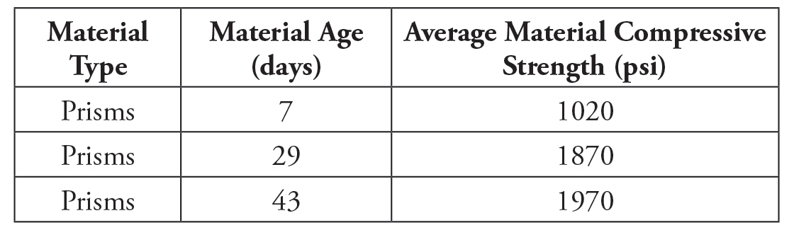
Table 1. Grout-filled CMU prism compressive strength data.
Crack Generation
To validate the test results, and to simulate possibly unfavorable field conditions, the crack width must be roughly constant over the depth of the masonry member. Furthermore, the crack must run approximately perpendicular to the surface of the test member to ensure that the axis of the anchor is in the plane of the crack.
To form a crack in the masonry members, splitting wedges were used, consisting of two halves of an expansion sleeve and a wedge. In this method, three or four splitting wedges were used across the width of the test member. Holes were then drilled through the masonry along a line at the desired crack location. After the expansion sleeves were placed into the holes, the wedges were sequentially hammered into the expansion sleeves until the masonry cracked along the line of the wedges. The crack was then closed by taking out the wedges. Anchors were then installed and the crack was re-opened to the desired width. Two dial gauges were placed on either side of the anchor to measure the crack width. Figure 2 shows the testing set-up used for initiating the crack and opening it to a specific width.
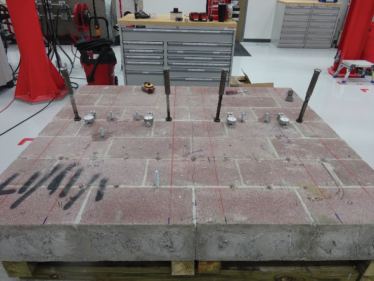
Figure 2. Generating a crack in masonry members for anchorage testing.
Note that reinforcement (less than 1% of the cross-sectional area of the masonry members parallel to the plane of the crack) was used to restrain the masonry wall during the cracking process.
Main Parameters and Test Series
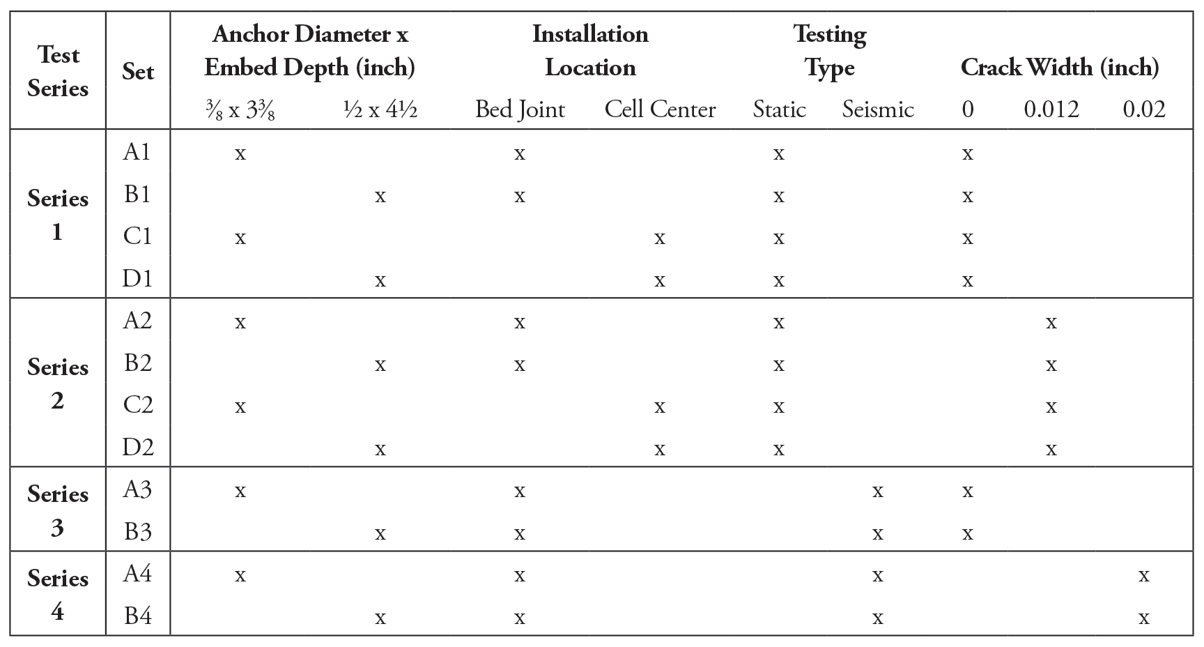
Table 2. Overview of parameter combinations used in experimental work.
A total of 4 test series were performed, with each series consisting of 2 to 4 sets (each set includes approximately five individual tests), to test the post-installed adhesive anchor systems in the cracked grout-filled CMU wall. As indicated above, the adhesive anchor system used threaded rods (3⁄8-inch and ½-inch-diameter rod sizes) to perform the confined static and seismic tension tests. The entire test matrix for the 60 tests is shown in Table 2. Test Series 1 and 3 are static and seismic tension tests of anchors installed in uncracked masonry members. Test Series 2 and 4 are static and seismic tension tests of anchors installed in cracked masonry members. Tests were performed at different locations in the CMU wall, including at the bed joint (or mortar joint) and at the center of the block cell as shown in Figure 3. Note that seismic test Series 3 and 4 were performed only on the anchors installed at the mortar joints since it was expected the mortar joint would be significantly affected by a seismically induced crack condition.
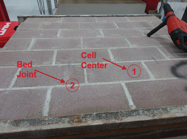
Figure 3. Anchor locations used for testing: 1) cell center; 2) bed joint (or mortar joint).
Static Tension Test Results
From the confined tension test results, values of the bond stress were derived for various rod diameters, d, and embedment depths, hef. Figures 4 and 5 show the anchor configuration as well as the confined tension test set up. Assuming a uniform stress distribution along the short bond length, the force Ns in the threaded rod is transferred to the masonry over the embedment length, resulting in a mean bond stresses τb,o of: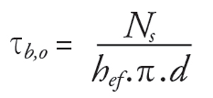
In this experimental work, two values were of particular interest: the Mean Bond Strength ( τb,o,m), and the Coefficient of Variation (COV) of bond strength. COV measures the dispersion of data points in a data series around the mean. It is a useful statistic for comparing the degree of variation. A small scatter indicates that the data points tend to be very close to the mean and each other. A high scatter indicates that the data points are spread out from the mean, and one another.
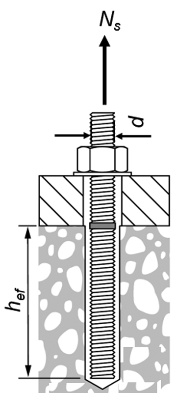
Figure 4. Anchor specification.
Table 3 summarizes the results of static tension tests for anchors installed at different locations (bed joint and center of the cell) in cracked and uncracked masonry members. In the uncracked condition, the mean bond strength obtained from various test series was in the range of 2,200 to 2,300 psi with a low COV. However, in the presence of a crack, the mean bond strength was reduced up to 26% compared to the uncracked condition, and the COV increased up to 13%. Note that although COV values of test series in cracked masonry were high, they were still in the acceptable range (below 20%) for a valid and reproducible test.
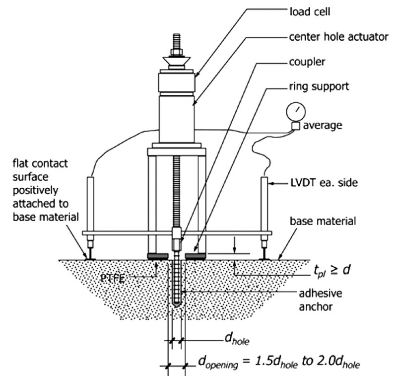
Figure 5. Example of the confined tension test setup.
In adhesive anchor systems installed in the masonry members, the load is transferred from the anchor to the masonry material by bond stresses. The bond between the drilled hole surface in the masonry and the adhesive must be reduced when the base material cracks. This condition leads to lower bond stresses compared to that of the uncracked condition, as can be seen from the test results. The large scatter of test results in the cracked condition can be explained by the random flow of the crack around the hole and along the anchor depth; this reflects the reduced performance of the adhesive anchor.
Table 3. Results of static pull-out tests.
Seismic Tension Test Results
Simulated seismic tension tests in cracked and uncracked masonry members were performed according to the procedure recommended by ACI 355.4-11. In this procedure, the anchors under testing are subject to the sinusoid varying loads, as shown in Figure 6, using a loading frequency between 0.1 and 2 Hertz (Hz). After the simulated seismic-tension cycles were run, the anchors were tested to failure to obtain the mean residual tension capacity.
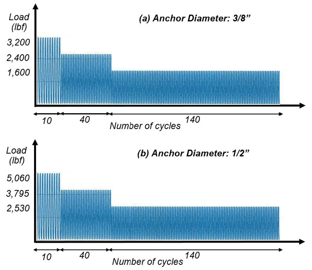
Figure 6. Cyclic load amplitude pattern used for seismic testing.
It should be noted that some anchors in set A4 (3⁄8-inch anchors in the cracked condition) failed before the completion of the seismic-tension cycles. For those that did not fail, their residual strength was found by testing them to failure under consistently increasing load. Table 4 summarizes the ultimate bond capacity of the anchors after completion of the cyclic loading part. In summary, all anchors installed in uncracked masonry members passed the cyclic part of the seismic test. However, in cracked masonry members, the 3⁄8-inch anchor failed during the first sequence of cycling. Tests with the ½-inch anchors in the cracked condition passed the cyclic loading, but bond residual strength was reduced by up to 30% compared to the uncracked condition.
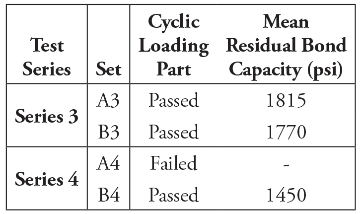
Table 4. Experimental results of seismic tension tests.
Implications for Design
Current guidelines and standards do not take into account the effects of cracking in masonry on anchor performance. Limited test data indicates that there can be a significant reduction on anchor capacity when cracks are present. The design implications of the experimental observations of a reduced strength due to cracking have not been fully identified. More work is required to develop appropriate design provisions in this regard.
Summary
In the absence of provisions to account for the influence of cracks on anchor performance in masonry, the Concrete and Masonry Anchor Manufacturers Association (CAMA) has started work to develop a procedure for post-installed adhesive anchor testing and qualification in cracked masonry members. In this regard, an experimental program was performed to examine the possibility of performing tests in cracked masonry and to preliminarily investigate the impact of cracking on anchor performance.
In summary, the procedure used in the experimental program for generating a stable crack in grout-filled CMU members and for testing anchors was successful in obtaining valid and reproducible test results. Testing of anchors in cracked masonry was not significantly different from testing in uncracked masonry; however, additional equipment was needed to form and control cracks. On the other hand, limited data from this testing proved that the performance of the anchor in masonry can be significantly affected by the presence of cracks and should not be ignored.■