
As the building industry forges ahead with technology and innovation, designers are encouraged to develop structures that perform as never before possible. Particularly in zones of high seismic activity, structures with large open spaces and high ceiling heights may not have seemed practical before the introduction of systems such as multi-tiered braced frames (MTBF). However, specific requirements for designing these MTBF systems are now defined in the Seismic Provisions for Structural Steel Buildings, ANSI/AISC 341-16, referred to as the 2016 AISC Seismic Provisions. This provides support both for these structures and for the seismic design industry.
What is a Multi-tiered Braced Frame?
In an MTBF system, two or more panels of bracing are stacked vertically within a single story. As shown in Figure 1, these braces can be built using common configurations, such as X-bracing, V-bracing, and chevron bracing. At intermediate levels between floors, horizontal struts span between each panel and transfer axial loads between the braces. The columns are typically I-shaped members oriented such that column buckling out-of-plane of the frame is about the major axis. The columns are braced in the plane of the frame by the struts, thereby reducing the minor axis unbraced lengths. Along the lines of braced frames, gravity columns outside of the MTBF can also be tied in at each strut level to take advantage of these reduced unbraced lengths. MTBFs are commonly found in buildings likely to have tall story heights, such as stadiums and other sports facilities, industrial steel structures, performing arts centers, airplane hangars, warehouses, and convention halls. Even multistory buildings with individual, tall story heights can make use of this system.
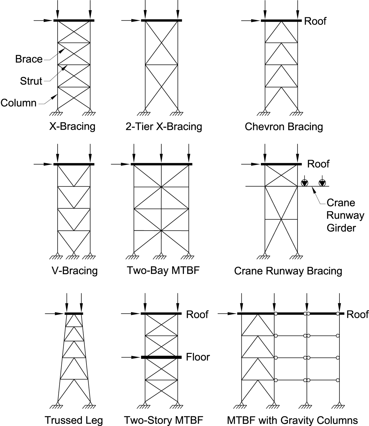
Figure 1. Typical configurations for MTBF.
Why Use a Multi-tiered System?
Braced frame systems are extensively used when designing buildings to resist seismic loads; they are inherently stiff and are designed to efficiently dissipate energy from an earthquake by yielding at predetermined locations. However, for structures with tall story heights, it may be impractical to configure a single brace from floor to floor and still effectively resist the lateral loads. For a given bay width, a taller story height results in a longer brace that is oriented at a steep angle relative to the horizontal force. This increased brace slenderness requires a larger member size to resist axial forces and reduces the number of available steel shapes that will meet the seismic ductility requirements found in the 2016 AISC Seismic Provisions. Also, the increased angle between the brace and the floor is not as efficient in its primary purpose of resisting horizontal loading as if it were oriented more horizontally. For these structures, using an MTBF system in place of a conventional braced frame addresses these concerns while still achieving the same desired building behavior.
How Does an MTBF Behave During an Earthquake?
As with other steel seismic systems, an MTBF is designed so that specific members within the frame yield during large earthquakes. This yielding, or ductile behavior of these members, absorbs a large amount of energy from the earthquake and dissipates it through inelastic mechanisms such as lengthening, bending, or buckling of the steel. This deformation is designed to occur specifically in the braces of MTBF, which then protects other members such as columns and struts from experiencing similar damage during the earthquake.
Brace buckling typically occurs in the weakest tier based on differences in brace size or tier height. When these factors affecting tier strength are designed to be identical between tiers, small imperfections in material or geometry will instead determine this initial buckling location at any one of the tiers. Buckling will then propagate through the remaining tiers until each compression brace has buckled. Following this intended buckling behavior, the horizontal compression struts then play a critical role in engaging the tension braces and maintaining a complete load path between floors. The struts and braces essentially behave as a vertical truss spanning between lateral supports at floor diaphragms. Without these struts, the tension braces would impose significant transverse loads into the columns.
What Is Permitted in the 2016 AISC Seismic Provisions?
Before the 2016 AISC Seismic Provisions, an MTBF system was classified as k-bracing and was thus restricted in practice. In a k-bracing configuration, two or more braces frame into a column at a point lacking any lateral support from inframing beams, struts, or a diaphragm. Therefore, the unbalanced forces from tension braces due to buckled compression braces induce large flexural forces into the column. Without a compression strut to resolve this lateral load, the system is inherently unstable and therefore prohibited in seismic design.
With the publication of the 2016 AISC Seismic Provisions, the MTBF classification is introduced with guidance for designing this system that uses horizontal struts to prevent the flexural forces from developing in the column to the extent that they do in k-frames. The Provisions address MTBF systems for use as ordinary concentrically braced frames (OCBF) in Section F1.4c, special concentrically braced frames (SCBF) in Section F2.4e, and buckling-restrained braced frames (BRBF) in Section F4.4d. Note that eccentrically braced frames (EBF) are excluded from this list because it is considered impractical to meet the link beam bracing requirements at intermediate levels with no inframing beams or diaphragm support.
What is so Special About MT-SCBF?
As one would expect, MTBF systems in regions with the highest level of seismic activity require the most ductility to dissipate earthquake energy. Multi-tiered special concentrically braced frames (MT-SCBF) are designed to accommodate brace buckling at each tier and the effects on adjacent struts, columns, and connections. Braces must be arranged in opposing pairs at each tier level to ensure that, for each direction of loading, one brace in tension has the tensile strength to support the earthquake loads after the other brace in compression has buckled. Figure 1 illustrates these pairs of tension and compression braces at each tier.
Even with the struts resolving the unbalanced horizontal load between tiers, some flexure is still induced into the columns. Because the compression braces in a single MTBF do not all buckle simultaneously, there are discrete moments when individual buckled tiers experience larger horizontal drift than those that have not yet buckled. As shown in Figure 2, this uneven drift at each tier up the height of the column results in column flexural forces in the plane of the frame. The amount of drift at each tier needs to be limited so that the ductile braces do not fracture while cycling between tension and compression during an earthquake. The MTBF column stiffness plays a substantial role in ensuring that tier drifts remain within acceptable levels. The column design must also consider out-of-plane forces, such as the effects of building mass on the structure or braces buckling out of plane, which can contribute to column instability. Overall, whereas other braced frame systems depend primarily on brace behavior, the columns in MT-SCBF are required to perform adequately in flexure and in stiffening the frame. Therefore, the AISC Seismic Provisions specify how to properly account for these column demands with additional analysis, design, and detailing. Columns are required to be torsionally braced at each tier level; this is typically satisfied through the connection to a strut that has adequate flexural strength and stiffness to perform this function.
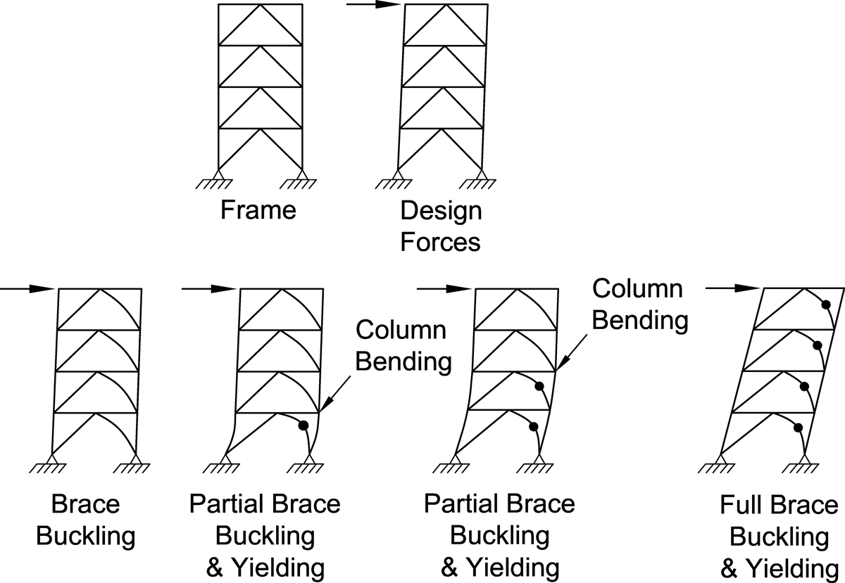
Figure 2. Progression of brace buckling and yielding in MT-SCBF.
MT-SCBF brace connections are detailed so that buckling occurs either in-plane or out-of-plane of the frame using the same provisions as for designing SCBF braces. Based on the expected buckling behavior, the adjacent columns, struts, and connections are designed to accommodate these deformations at each tier. The resulting rotations impose additional flexure and torsion that must be considered in the design of these supporting struts and columns.
Would an MT-OCBF Have These Same Requirements?
Multi-tiered ordinary concentrically braced frames (MT-OCBF) are used extensively for buildings in regions of low seismicity whose conditions still invoke the AISC Seismic Provisions. Several of the same geometry configurations will apply in accordance with the definition of an MTBF: pairs of braces must be placed in opposing directions at each tier, struts must separate each tier between floors, and each column must be torsionally braced by these struts. However, the system does not need to be as ductile because of the lower level of earthquake energy in these regions, so the design requirements are relaxed when compared to those of MT-SCBF systems.
Design level forces are determined for each member in the frame, and the braces are sized accordingly. The columns, struts, and connections are then sized for these forces with an overstrength factor of 2, and an additional factor of 1.5 applied. The purpose of these increases in design forces is to ensure that any inelastic response occurs in the braces and not in any other elements or connections where such behavior would compromise the stability of the frame. For the columns, in particular, increasing the required strength is a simplified method of resisting any in-plane flexural demands due to nonuniform brace forces and drifts between tiers.
The lower ductility requirements also allow for the implementation of tension-only bracing, a system commonly used in non-seismic buildings, as long as additional provisions are satisfied. In this system, braces are only deemed effective in resisting seismic forces when they are loaded in tension, and any contribution from compression braces is ignored. To consider this a practical assumption, only those steel shapes with slenderness ratios of 200 or more may be used. Because buckling of these slender brace members does not impact the columns, struts, and connections to the same extent as in typical frames, those elements do not require the additional 1.5 factor on design forces. However, as with MT-SCBF systems, the lack of lateral support at intermediate tiers allows for progressive yielding in the frame. The column is therefore designed to resolve a portion of this unbalanced lateral loading as a flexural force. The AISC Seismic Provisions specify this loading as five percent of the larger brace strength horizontal component above or below each strut; this design consideration captures any potential differences in the strengths of otherwise identically specified braces due to material yield strength variability.
How Does This System Apply to MT-BRBF?
Multi-tiered buckling-restrained braced frames (MT-BRBF) are unique in that the braces in compression are designed to retain their full strength at large earthquake loads. While SCBF buckled compression braces provide significantly less resistance than tension braces, BRBF compression braces can reach a yield strength similar to the tension yield strength. This prevents the progressive buckling behavior between tiers that is found in other MTBF systems, and the MT-BRBF is therefore recognized as highly stable. This allows for even more possible brace configurations because braces do not need to be arranged in opposing pairs as with the systems previously discussed.
While both compression and tension braces exhibit ductile behavior through steel yielding, there still will be a load imbalance between tiers due to the compression strength adjustment factor applied to all BRBF compression braces. Even if all other factors (brace member size, steel grade, orientation, etc.) are uniformly defined, this adjustment factor creates a net horizontal load when both a tension and a compression brace frame into a single node. Furthermore, even if two identical braces are oriented in the same direction, the 2016 AISC Seismic Provisions require that each intermediate level in the frame account for a horizontal notional load equal to 0.5 percent of the adjacent tier, with the higher strength based on its adjusted braced strengths. The purpose of these minimum horizontal loading requirements is to account for quantifiable load imbalances as well as those caused by varying brace strains, tolerances in BRBF steel core cross-sections, and small differences between tested and installed core yield strengths.
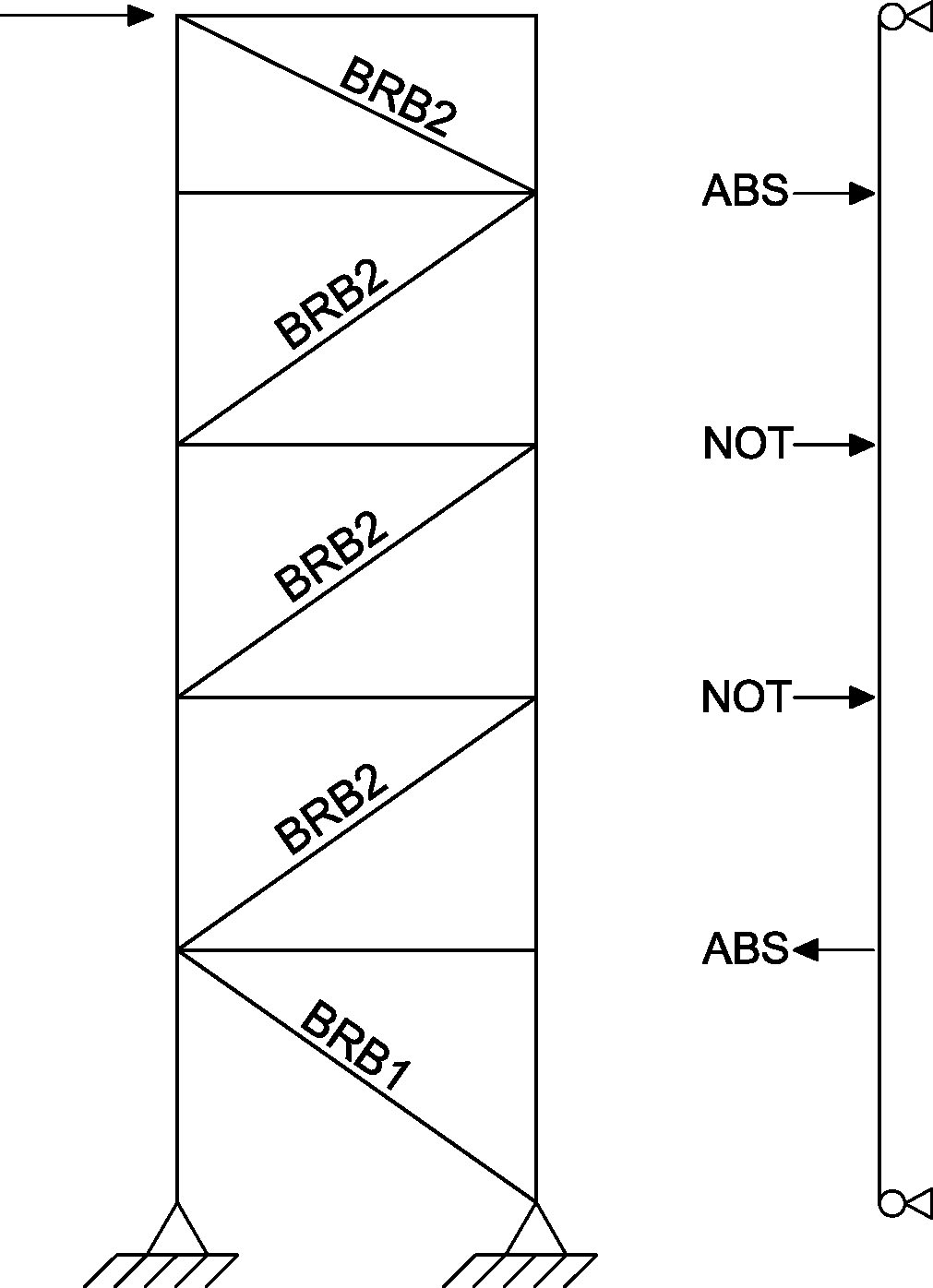
Figure 3. MT-BRBF column design loads.
Figure 3 illustrates how these different absolute and notional loads are accounted for in the frame design. The “ABS” annotation between the lowest two tiers represents an absolute loading that occurs on account of two different specified BRBF cores. The absolute loading at the top two tiers is based on varying tier heights that affect the horizontal force components for each brace. At the remaining levels, the identical BRBF braces and orientations would not result in load imbalances and instead are designed for notional “NOT” loads. The columns are then designed to resolve these loads in flexure at each tier, as shown in Figure 3. To not penalize a single column, these loads may be shared between a series of columns so long as the struts account for this load path and the design accounts for the simultaneous compression loading in the column. The same requirement for other MTBF systems to torsionally brace the columns at each strut level applies to MT-BRBF columns as well.
Brace for the Future
With the introduction of MTBF into the AISC Seismic Provisions, designers now have the tools available to expand the scope of buildings that can withstand seismic forces. While the actual magnitude and location of the next big earthquake remain unpredictable, this structural steel system provides the strength and reliability needed to withstand such an event.■