
Part 2: Beams
This article is the second in a series on recommended reinforcement details for cast-in-place concrete construction. The first article, on Two-Way Slabs, ran in the June 2019 issue of STRUCTURE.
Detailing Flexural Reinforcement
Once the size of the cross-section of a beam has been determined based on serviceability and strength requirements, the required area of flexural reinforcement, As, is calculated by setting the required flexural strength, Mu, equal to the design flexural strength, Mn. The size and number of reinforcing bars must be chosen to (1) provide an area of reinforcement equal to or greater than the amount that is required, and (2) satisfy the minimum and maximum spacing requirements in ACI 318-14, Building Code Requirements for Structural Concrete and Commentary.
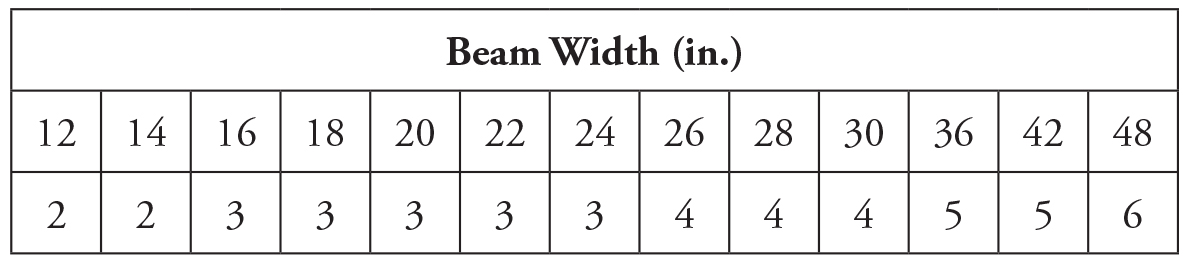
Table 1. Minimum number of reinforcing bars required in a single layer.
Reinforcing bars that are spaced too far apart could result in relatively large flexural crack widths. Thus, the maximum center-to-center spacing, s, of the deformed longitudinal bars to limit crack widths is given by the following equation (see ACI Table 24.3.2):
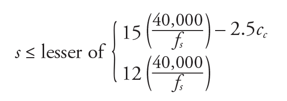
where fs is the calculated stress in the flexural reinforcement closest to the tension face of the section due to service loads and cc is the least distance from the surface of the reinforcement to the tension face of the member. It is permitted to assume that fs = 2fy/3 where fy is the specified yield strength of the reinforcement. Table 1 contains values of the minimum number of bars required in a single layer for various beam widths based on Grade 60 reinforcement (fs = 40,000 psi), cc = 2 inches (1.5-inch cover plus the diameter of a #4 stirrup), and the overall longitudinal reinforcing bar diameter (approximate diameter to the outside deformations of the bar), which is given in Table 2.
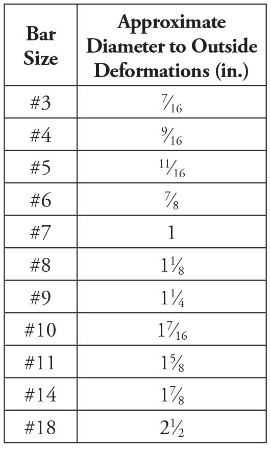
Table 2. Overall reinforcing bar diameter.
Minimum spacing between the longitudinal bars is required to adequately place the concrete; concrete may not be able to flow in the voids between the bars if the bars are spaced too closely together, especially with concrete mixes with larger aggregates. According to ACI 318-14, Section 25.2.1, the minimum clear space between reinforcing bars must be at least equal to the greatest of 1 inch, db, or (4dagg/3) where db is the nominal diameter of the longitudinal reinforcing bars and dagg is the nominal maximum size of coarse aggregate in the concrete mix. Table 3 contains the maximum number of bars that can fit in a single layer for various beam widths based on Grade 60 reinforcement, the overall reinforcing bar diameter, 1.5-inch cover to the beam stirrups, dagg = 3⁄4 inch, #3 stirrups used with #4, #5, and #6 longitudinal bars, and #4 stirrups used for #7 and larger longitudinal bars.
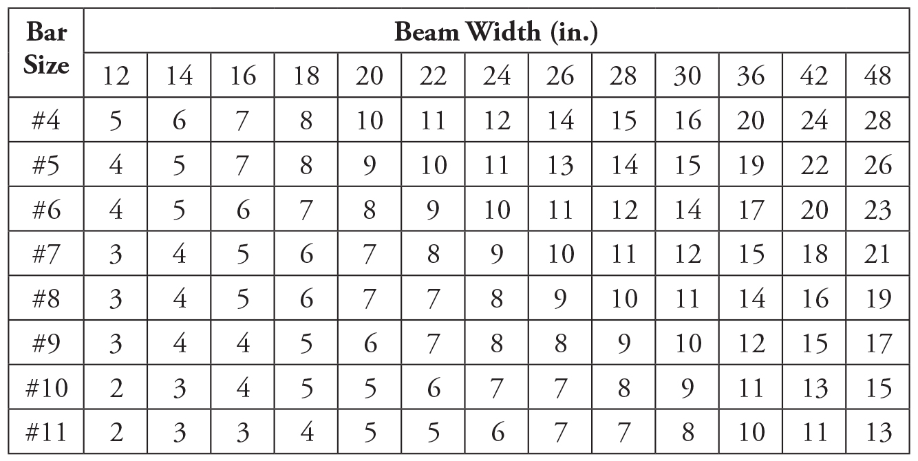
Table 3. Maximum number of reinforcing bars permitted in a single layer.
Selecting the number of longitudinal bars within the limits of Tables 1 and 3 provides automatic compliance with the ACI 318 requirements for cover and spacing, given the assumptions noted above. The minimum clear spacing requirements of ACI 318-14, Section 25.2.1, are also applicable to contact lap splices and adjacent splices or bars. Using the largest practical bar sizes that satisfy these requirements usually results in overall cost savings.
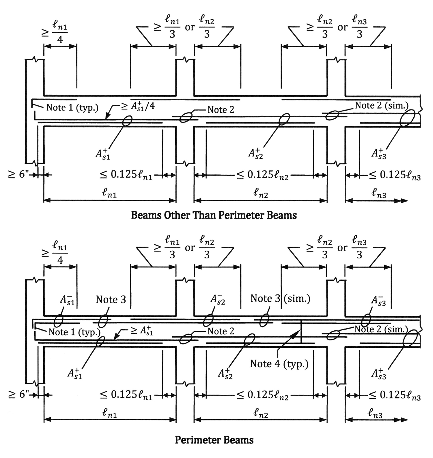
Figure 1. Recommended bar extensions for flexural reinforcement in beams subjected to uniformly distributed gravity loads.
ACI 318-14, Section 9.7.3, contains the requirements for the development of reinforcing bars in beams. For beams subjected to uniformly distributed gravity loads where the shape of the moment diagram is known, the development lengths in Figure 1 can be used. These recommended details include the requirements for structural integrity reinforcement in ACI 318-14, Section 9.7.7, and can be used for beams that have been designed using the approximate bending moment coefficients in ACI Table 6.5.2. The Notes in Figure 1 are as follows:
- Reinforcement to be anchored to develop fy at the face of the support. (Standard hooks are depicted in Figure 1.)
- At least the larger of (A+s1/4) or (A+s2/4) but not less than 2 bars must be continuous or spliced with Class B tension splices or mechanical or welded splices.
- At least the larger of (A‒s1/6) or (A‒s2/6) but not less than 2 bars must be continuous or spliced with Class B tension splices or mechanical or welded splices.
- Closed stirrups in accordance with ACI 318-14, Section 25.7.1.6, or hoops must be provided along the clear span.
- Where the requirements in Note 2 are not satisfied for beams other than perimeter beams, closed stirrups in accordance with ACI Section 25.7.1.6 or hoops along the clear span must be provided.
For simpler detailing, all the bottom bars are often extended the entire span instead of cutting off a portion of them, as shown in Figure 1.
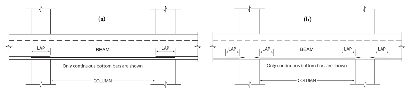
Figure 2. Splice arrangement for bottom bars in a reinforced concrete beam: a) All bottom bars spliced over the column; b) Separate splice bars provided in the beam-column joints.
Lapping of continuous bottom bars at supports often presents congestion and installation problems. For example, it is common to splice all the bottom bars over the columns away from the section of maximum positive reinforcement, as shown in Figure 2a. This arrangement is the simplest to detail and is most suitable where the beams are wider than the columns. However, it can result in congestion in the beam-column joints. One way to circumvent this issue is to use the detail in Figure 2b: splice bars are provided in the joint, which are spliced to the bottom bars on both sides of the joint. This arrangement works very well with preassembled beam cages because no bottom bars pass through the column during installation. Even though this arrangement increases the amount of reinforcing steel that is required, the cost of the additional material may be more than offset by the savings in labor and other costs; it may be the most cost-effective arrangement in certain situations.
Detailing Shear Reinforcement
To avoid potential congestion issues at beam-column joints, it is good practice to specify beams that are at least 4 inches wider than the columns into which they frame. As floor systems become shallower (which also leads to overall economy), beams generally need to become wider. Proper stirrup detailing in wide beams is essential to ensure that the longitudinal flexural reinforcement and the stirrups are fully effective.
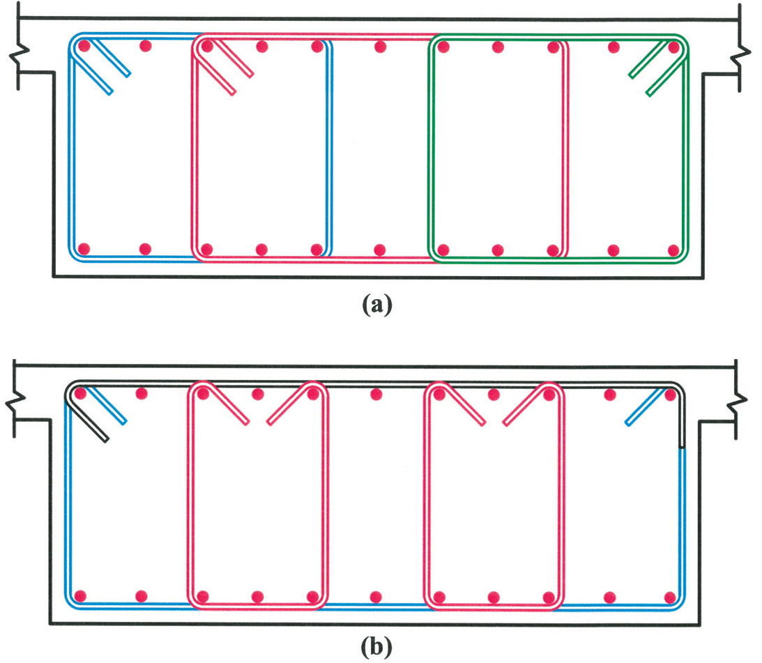
Figure 3. Beam stirrup configurations: a) Three one-piece, closed stirrups distributed across the beam width; b) Alternate stirrup configuration with open stirrups and stirrup caps.
Research has shown that locating stirrups solely around the perimeter of a wide beam is not fully effective. Thus, stirrup legs are required in the interior of a wide beam. A common stirrup configuration is illustrated in Figure 3a, where three closed stirrups are provided. One problem with this configuration is that none of the stirrups traverse the full net width (that is, the full beam width minus the total side cover) of the beam. Thus, the overall width of the stirrup arrangement needs to be measured and verified in the field before installation, which translates to extra time and cost. During installation, it is possible for the net width to change when the preassembled cage is hoisted into position by crane; this increases the possibility that the provided cover will be less than that which is required. Another problem may occur where the stirrups are built in place instead of preassembled: one-piece closed stirrups make it challenging to place all the required longitudinal reinforcement in the beam, especially where large, long longitudinal bars must be threaded through the stirrups.
In the configuration illustrated in Figure 3b, a single, open stirrup is provided that extends the full net width of the beam. A stirrup cap consisting of a horizontal bar with a 135-degree hook at one end and a 90-degree hook at the other end is provided at the top of the configuration, which also extends the full net width of the beam. Providing a full-width stirrup helps in maintaining the correct concrete cover and facilitates installation of the beam reinforcement: longitudinal bars can be placed easily within the beam from the top before installation of the stirrup cap. Two sets of identical U-stirrups with 135-hooks are shown symmetrically placed within the interior of the beam. This configuration provides a cost-effective way of providing shear reinforcement for wide beams.
Drip Grooves
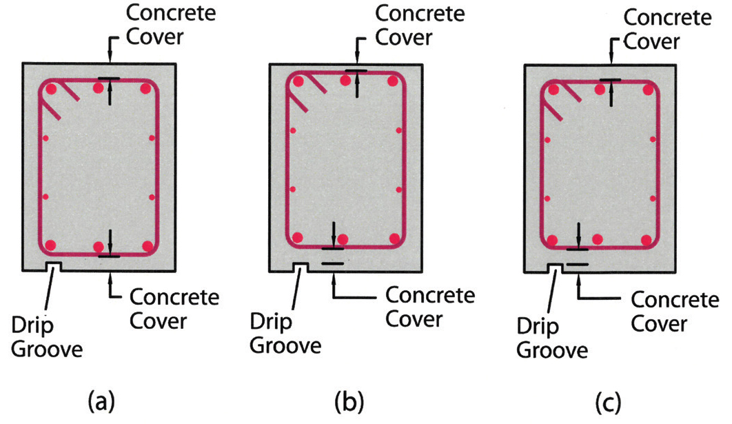
Figure 4. A beam with a drip groove on the bottom soffit: a) Inadequate bottom cover at the drip groove; b) Shifting the reinforcement cage upward causes inadequate top cover; c) Adequate concrete cover provided at both the top and bottom surfaces.
A drip groove or edge in a beam often presents a problem in maintaining the required cover to the reinforcement in the beam (Figure 4a). It is frequently not feasible to increase the concrete cover after the bars in the beam have been detailed. Raising the stirrups from the bottom to achieve the required bottom cover decreases the top cover (Figure 4b). A practical solution is to measure the concrete cover to the drip groove and detail the stirrups accordingly, as shown in Figure 4c. This impacts the overall effective depth to the flexural reinforcement and needs to be accounted for in the design.
Beam Intersections
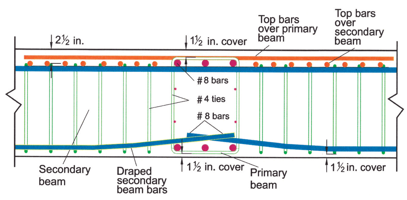
Figure 5. Layering of beam and slab reinforcing bars at beam intersections.
Maintaining the proper concrete cover can also be challenging at beam intersections (Figure 5). In particular, layering the top steel in the slab at such intersections can create constructability issues. The sequencing and layering of beam and slab top reinforcement can also create congestion issues. The following sequence for bar placement is one way of avoiding problems associated with these intersections:
- Erect the reinforcement for the primary beams (bottom bars, stirrups, and top bars) as stand-alone cages and set in place.
- Place the stirrups (bottom pieces of two-piece stirrups) and the bottom bars for the secondary beams.
- Place the bottom bars for the slab (not depicted in Figure 5 for clarity).
- Place the top bars and the top pieces of the two-piece stirrups for the secondary beams.
- Place the top bars for the slab.
Additional recommendations for detailing of reinforced concrete beams, including detailing guidelines for torsional reinforcement, steps in beams, and for beams in building assigned to Seismic Design Categories C through F can be found in the CRSI publication Design Guide for Economical Reinforced Concrete Structures.■
References
ACI (American Concrete Institute). 2014. Building Code Requirements for Structural Concrete and Commentary. ACI 318-14, Farmington Hills, Michigan.
CRSI (Concrete Reinforcing Steel Institute). 2015. Reinforcing Bar Detailing. Schaumburg, IL.
CRSI (Concrete Reinforcing Steel Institute). 2016. Design Guide for Economical Reinforced Concrete Structures. Schaumburg, IL.