
Superior Court of California
The new San Diego Central Courthouse is a bold and iconic civic landmark that replaces the seismically vulnerable existing courthouse facility. The new Superior Court of California, San Diego Central Courthouse consolidates San Diego County’s criminal trial, family, probate, and civil courts into a 704,000-square-foot downtown facility integrated with the neighboring hall of justice and county jail facilities. The new courthouse, comprising a full city block, includes 71 courtrooms and consists of a 24-story 396-foot-tall tower and 4-story podium clad in glass and precast concrete with two below grade basement levels (Figure 1).
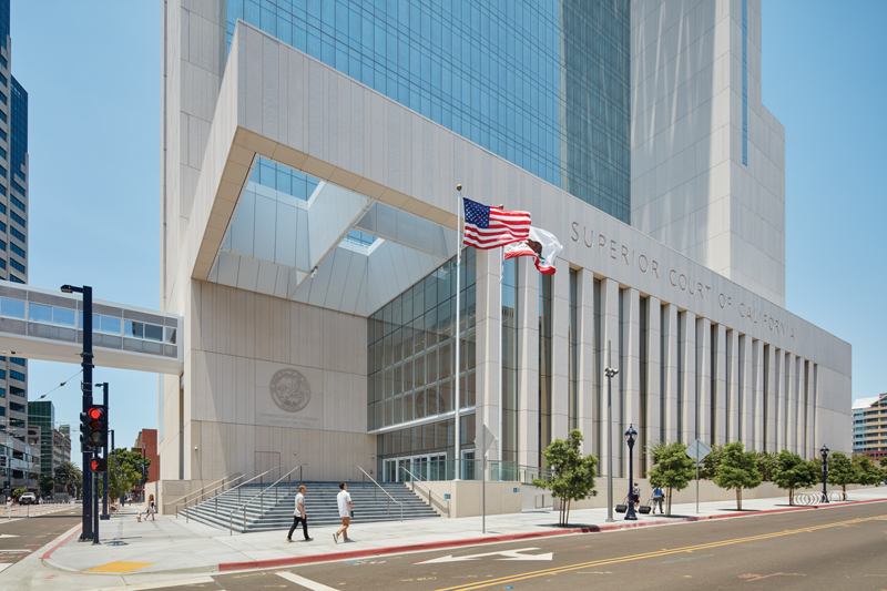
Figure 1. View of new San Diego Central Courthouse at the main entrance. Courtesy of Bruce Damonte.
The courthouse replaces the adjacent existing courthouse facility built over an active earthquake fault zone. Designed for the Judicial Council of California (JCC) by the Skidmore, Owings & Merrill LLP (SOM) – Architecture, Structures, Interiors, and Graphics team working closely with the client and a group of trusted consultants – a complex set of site, programming, and cost constraint challenges were solved. The design achieves a high level of integration and efficiency while meeting client enhanced-seismic performance objectives. The facility construction was led by the Rudolph & Sletten (R&S) construction manager and contractor team which began in March 2014 and was completed in June 2017.
Site Selection and Context
The assessment program, conducted in accordance with the California Trial Court Facilities Act of 2002 (CA Sen. Bill 1732), found that the existing San Diego County Courthouse/Old Jail building structures (built 1957-1962) were exposed to significant seismic risks. Seismic fault studies indicated that a projection of the known San Diego Fault runs through the northern and central portions of the existing County Courthouse/Old Jail site located in the central downtown San Diego district (Figure 2). For this reason, a new facility site location was investigated to fall outside the limiting 50-foot setback from a potential earthquake fault. A site was selected one block west of the existing facilities where, based on previous seismic fault studies, no active or potentially active faults were known to occur. Project-specific fault rupture boring and fault trenching investigations later confirmed that the site is not underlain by an active or potentially active fault. The new courthouse design accommodates a future underground tunnel planned to connect the courthouse with the county jail facility. Additionally, at the third level of the new courthouse, a pedestrian bridge connects with the existing Hall of Justice to the south. This bridge is supported by one tapered bridge bent column located within the sidewalk setback. The pedestrian bridge features an 85-foot cantilevered orthotropic steel deck structure to avoid placing new loads on the existing Hall of Justice.
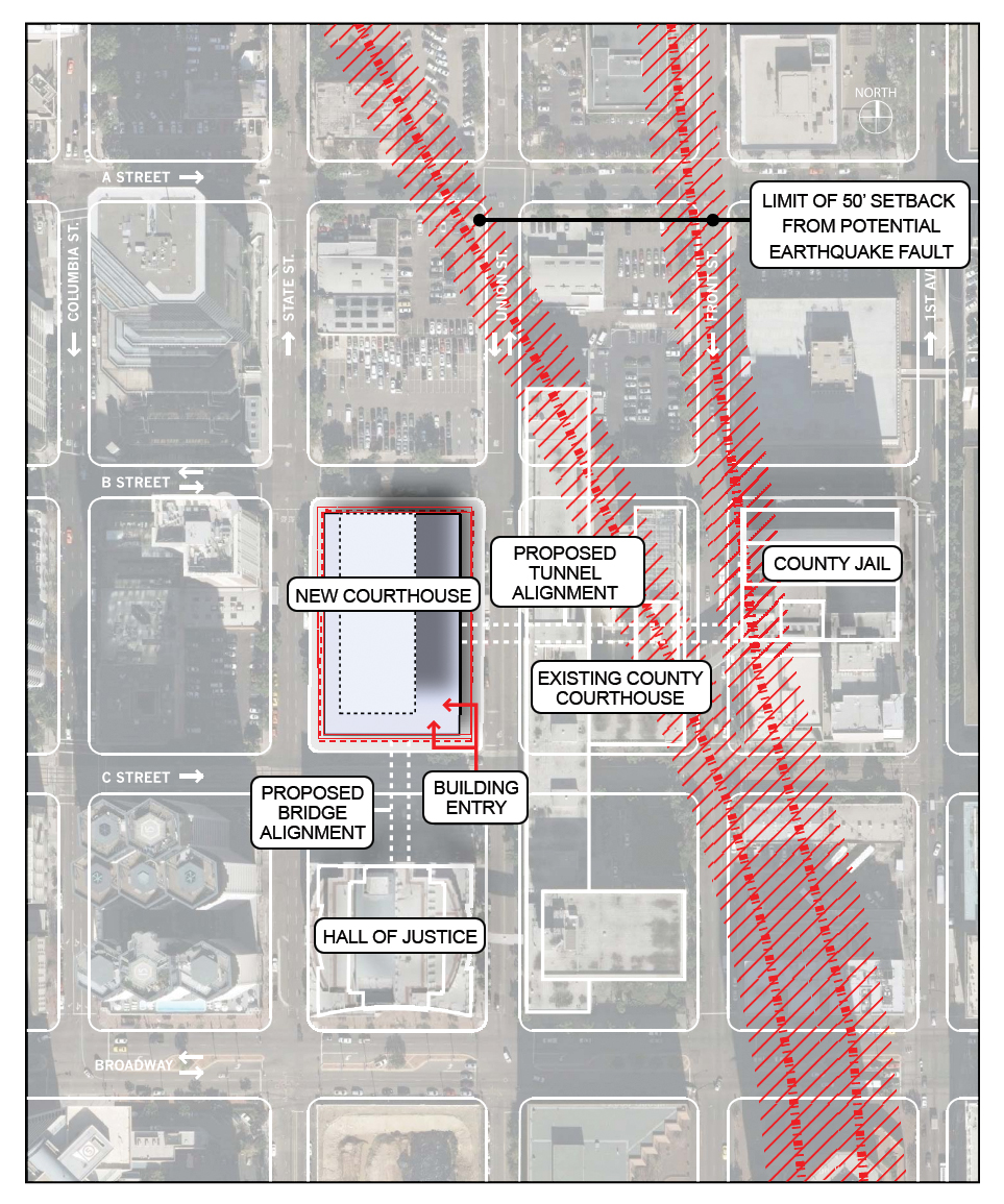
Figure 2. Site selection relative to existing fault lines.
Enhanced Seismic Design
Recognizing that the new San Diego Central Courthouse lies in a region of high seismicity, and in close proximity to active and potentially active downtown San Diego earthquake fault zones, the 24-story above-grade and two levels below grade structure was designed to meet “enhanced” seismic performance objectives of the Judicial Council of California (JCC), California Trial Court Facility Standards (CTCFS, 2011) and the 2010 California Building Code (CBC). In compliance with requirements of CBC Table 1604.5, a risk Occupancy Category III was assigned to the design of the courthouse in recognition of “Buildings and other structures that represent a substantial hazard to human life in the event of failure, … whose primary occupancy is public assembly with an occupant load greater than 300.” Therefore, an increased Importance Factor, I = 1.25 per ASCE 7-05 Table 11.5-1, was used in the seismic design calculations. Additionally, the risk Occupancy Category III criteria required a more restrictive seismic story drift limit of 1.5% of story height.
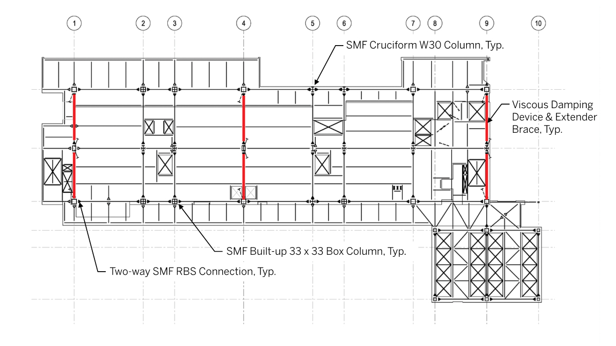
Figure 3. Typical tower steel gravity composite and lateral SMF + VDD framing plan.
In accordance with CTCFS (2011) Chapter 12, Criteria for Rare Loads – Earthquake, the “normal” seismic performance of all new JCC facilities is intended to be above average to buildings designed by minimum prescriptive building code provisions. Due to its regional importance, close proximity to active earthquake faults, and public assembly occupant loads, the San Diego Central Courthouse was designated to be designed for an “enhanced” seismic performance objective. Enhanced performance is intended to limit damage and potential loss of use.
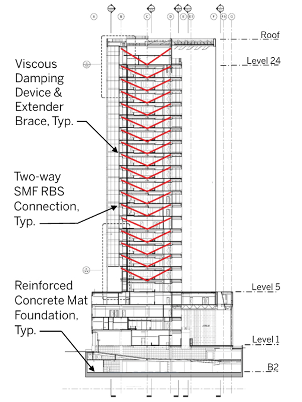
Figure 4. Transverse building section with frame VDD.
The courthouse superstructure seismic force resisting system consists of distributed and redundant ductile steel “special moment frames” (SMF) with “reduced beam section” (RBS) qualified connections in both the transverse (E-W) and longitudinal (N-S) building directions (Figures 3 and 4). The SMF wide flange steel beams dissipate energy during strong earthquake ground shaking, while large SMF steel cruciform wide flange and built-up box columns provide stability and strength to transfer vertical gravity and lateral loads. A total of 106 viscous damping devices (VDD) with extender braces are interconnected with the SMF columns and distributed along the height of the structure in the transverse (E-W) direction from Level 6 to the roof at Level 25. Configured in 2-bays on each of three column grid lines, the damping devices act to reduce earthquake-induced building story forces, drifts, and accelerations to provide enhanced seismic performance under peak demand of a CBC Maximum Considered Earthquake (MCE) magnitude with a 2,475-year average return period.
By controlling peak story drift demands, a reduction of inelastic deformations on the superstructure steel SMF connections is achieved. The enhanced performance also results in a reduction in damage to nonstructural building components including both acceleration-sensitive and deformation-sensitive elements. These components include exterior wall elements, interior partition walls, circulation and courtroom finishes, as well as anchorage of suspended ceilings, lighting fixtures, fire sprinkler/protection lines, HVAC/MEP distribution and equipment, elevator guide rails/bracing, and egress stair elements. Potential damage to building contents including desktop electronics, office workstations, lateral filing cabinets, and shelving is also reduced. In summary, the structure of the courthouse was designed to withstand the seismic forces of a rare earthquake with less damage or disruption than a similar building designed to code-minimum standards.
Response-History Analysis and Design
In accordance with the prescriptive requirements of ASCE 7-05 Chapters 12, 16, and 18, a 2-stage approach was taken in the structural analysis modeling and design of the SMF + VDD seismic force resisting system. Response-history analysis using a suite of seven site-specific ground motions was used at both the Design Earthquake (DE) (475-yr) and MCE (2475-yr) earthquake hazard levels using sets of 7-pairs of ground motion orthogonal time history acceleration records representing fault normal (FN) and fault parallel (FP) components. In Stage 1, a linear elastic SMF (damping, ζ=5%) with nonlinear VDD model is used and, in Stage 2, a nonlinear SMF (damping, ζ=2.5%) with nonlinear VDD, both modeled using fast nonlinear analysis method (CSI ETABS Nonlinear, V9.7.4). Stage 1 analyses included 725 modes to capture both VDD nonlinear link elements and vertical masses; Stage 2 analyses included a total of 3000 modes capturing additional nonlinear link definition (FEMA 356) of the 2056 RBS steel connections. Four envelope FN and FP ground motion orientation analyses, for each DE and MCE earthquake level, were undertaken.
Additionally, the analyses are repeated to represent both lower bound and upper bound damper device properties (+/-15%) at each of the DE and MCE earthquake hazard levels as required by ASCE 7-05. Peak transverse DE drifts are shown in Figure 5. The direct analysis method introduced in AISC 360-05 was utilized; seismic design requirements of AISC 341-10 and AISC 358-10 were also satisfied.
Special Moment Frame Qualification Testing
Motivated by both a significant reduction in steel tonnage cost savings and improved enhanced seismic performance, testing of three full-scale specimens consisting of steel SMF with RBS connection to a large box column was undertaken during the construction document design phase. The project specific qualification testing allowed the use of larger box columns exceeding the AISC 358-10 box column width and depth limitation of 24 inches. Typical SMF beams in the project consist of W24 and W36 rolled shapes with a maximum size of W36x302. The SMF columns included both bi-axial W30 cruciform columns and bi-axial built-up box columns, typically 33-inch-square, ranging from 20- to 36-inch dimension. The three tests were conducted at UC San Diego testing laboratory in December 2012, January 2013 and April 2013, respectively. All three test specimens consisted of same size box column, 24- by 36-inch with 2-inch plates and RBS beam W36x302 section. Specimens #1 and #2 exhibited only marginally acceptable brittle fracture failure modes. Post-test investigations and analysis revealed several conditions that contributed to the non-ductile fractures. Detailing improvements, incorporated in Specimen #3 testing, successfully demonstrated overall ductility in conformance with AISC 341 and 358 acceptance criteria, with expected RBS behavior undergoing two cycles at both 4% and 5% drift levels (Figure 6).
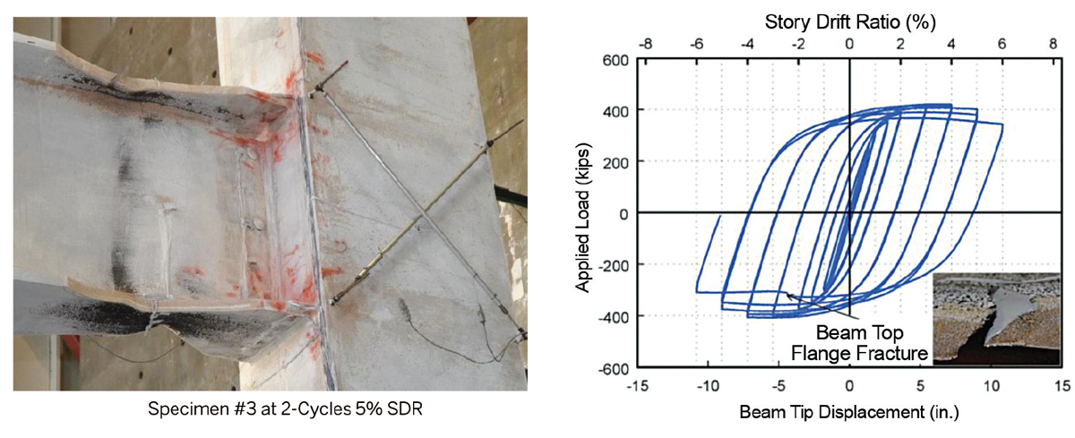
Figure 6. SMF Specimen #3 test results (UCSD).
Viscous Damping Device Energy Dissipation
Designing tall, slender structures with steel SMF renders architectural versatility and high ductility but presents a unique challenge in controlling story drifts due to its low elastic stiffness, especially for the typical 16-foot story height. The application of advanced supplemental fluid viscous damping device (VDD) technologies to these tall SMF structures is known to effectively reduce potential damage to the structure, non-structural elements, and building contents, as well as loss of use under expected moderate to major earthquake events. The new courthouse VDD energy dissipating system reduces seismically induced building story shears, story drifts, floor accelerations, and inelastic rotational demands on the steel SMF beam-column joints. The VDDs were further utilized to resist the low-amplitude, velocity-excited portion of wind loads with effective linear damping exceeding 11%. This was substantiated by wind tunnel modeling, analytical methods, and a damper prototype testing program in conformance with ASCE 7 (Figure 7).
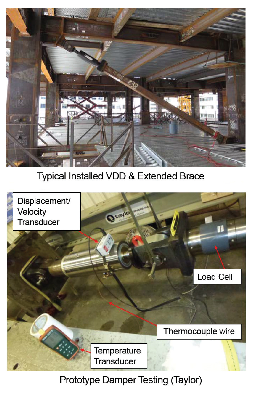
Figure 7. Viscous Damping Devices (VDD).
Strong Motion Instrumentation System
The new San Diego Central Courthouse has incorporated the installation of a strong motion instrumentation system to collect and process data obtained during strong earthquake ground shaking. The system was designed, specified and, procured during the base building design, construction document, and construction administration phases under the direction of the JCC and general contractor. Installation and commissioning support, and long-term maintenance of the system, is provided by the California Strong Motion Instrumentation Program (CSMIP), California Geological Survey, Department of Conservation, as part of the statewide network of instrumented buildings. A total of 28 accelerometers, 24 installed in the main building superstructure (19 horizontal and 5 vertical sensors) and 4 installed in the connecting cantilevered pedestrian bridge to the adjacent HOJ at Level 3 (3 horizontal and 1 vertical sensors) were provided. All accelerometers are interconnected to computer controlled digital recording equipment at Level B2 with cabling for a common start, GPS timing, and synchronization. At the tower roof level, a GPS antenna and junction box are installed to support the system. The system is triggered by the sensors located at Level B2 at a threshold of 0.5% g, and de-triggered by the sensors located at Levels 23 and 25 at approximately the same acceleration (0.5-1.0% g).
Conclusion
As structural engineers, it is not often that we are challenged to pursue design performance objectives that require extra effort, initiative, innovation, peer review, cost constraints, collaboration, and construction oversight – with the full support of client and user groups. This was the case for the design of the new San Diego Central Courthouse working with the Judicial Council of California and the San Diego Superior Court team’s leadership and well-established goals and objectives. In the design of the new courthouse, while meeting a range of complex design challenges – architectural integration, efficiency, physical security, sustainability, and cost control – a high priority was to achieve an “enhanced” seismic performance objective intended to limit damage and potential loss of use.■
References
Sarkisian, M., Lee, P., Garai, R., Ozkula, G. and Uang, C.M., (SOM et al., 2013a), Effect of Built-up Box Column Electro-slag Welding on Cyclic Performance of Welded Steel Moment Connections, SEAOC 2013 Convention, September 20, 2013, San Diego, CA.
Lee, P., Sarkisian, M., Garai, R., Uang, C.M. and Ozkula, G. (2014). Issues on Using Welded Built-up Box Columns in Steel Special Moment Frames, Proc., 10NCEE, Anchorage, AK.
Ozkula, G. and Uang, C. M. (2014), Cyclic Testing of RBS Moment Connections with Built-up Box Columns for the San Diego Central Courthouse Facility, Report No. TR-13/01, Department of Structural Engineering, University of California, San Diego, La Jolla, CA.
Sarkisian, M., Lee, P., Garai, R., Tsui, A. (2015). Controlling Wind in Tall and Flexible Structures with Viscous Damping Devices (VDD), Proc., SEAOC 2015 Convention, September 10, 2015, Seattle, WA.
Lee, P., Garai, R., Tsui, A. and Hua, Y. (2016). Special Moment Frame Qualification: RBS to Box Column, Proc., SEAOC 2016 Convention, October 14, 2016, Maui, Hawaii.
Sarkisian, M., Lee, P., Garai, R., Tsui, A. (2017). Enhanced Seismic Design Of The New San Diego Central Courthouse, Proc., SEAOC 2017 Convention, September 15, 2017, San Diego, CA.
Ozkula, G., Garai, G., Lee, P., Uang, C.M., (2019). “Cyclic Behavior of Electroslag Welded Joints in Beam-to-Built-up Box Column Steel Moment Connections”, ASCE Journal of Structural Engineering, Ms. No. STENG-6951R2.