
Preventing Tile and Stone Cracks
Two kinds of designers are sometimes involved in home construction – design professionals responsible for the structure and interior-focused designers responsible for the final appearance. Although these roles can overlap, it is important for design professionals to be aware of in-service demands that will result from interior finish choices.
There are three aspects of floor design likely to impact the performance of ceramic tile and stone installations in-service:
- The use of an adequate design dead load, which includes the weight of the hard-surface installation method,
- The relative importance of joist stiffness and sheathing stiffness in preventing cracks, and
- Accounting for substantial concentrated loads, such as the weight of kitchen islands with stone or polished concrete surfaces.
This article reviews these three aspects and offers guidance for designers and others interested in the structural performance of their products after construction.
Floors Supporting Tile and Stone
If the dead load (weight) of tile or stone “Installation Methods” by Design Professionals (DPs) are inadequately specified, wood-frame floors can be over-stressed in-service and excessive “creep deflection” can occur that causes cracked grout and tiles in-service. Specifying an adequate dead (sustained) load is essential for a reliable hard surface installation.
One way to think of “creep deflection” is to imagine an overloaded shelf in a bookcase. Over time, the weight of the books can cause the shelf to bow. The deformation is not visible immediately, but the damage can be permanent. In the case of a floor, not only is the effect on the floor itself an issue, but also the effect on the flooring. The “creep” occurs beneath the flooring, so the flooring is no longer on top of a level surface and the result can be cracking of tiles and grout.
Weight of Hard-Surface Installation Methods
Dead load data for the weights of tile and stone installations have been tabulated in Appendix B of the 2017 Tile Council of North America (TCNA) Handbook for Ceramic, Glass, and Stone Tile Installation (https://goo.gl/9acfZE). Appendix B is an invaluable design resource that contains the typical weight of dozens of “Installation Methods” for ceramic and glass tile (hereafter, tile) and stone installed on wood-floor framing.
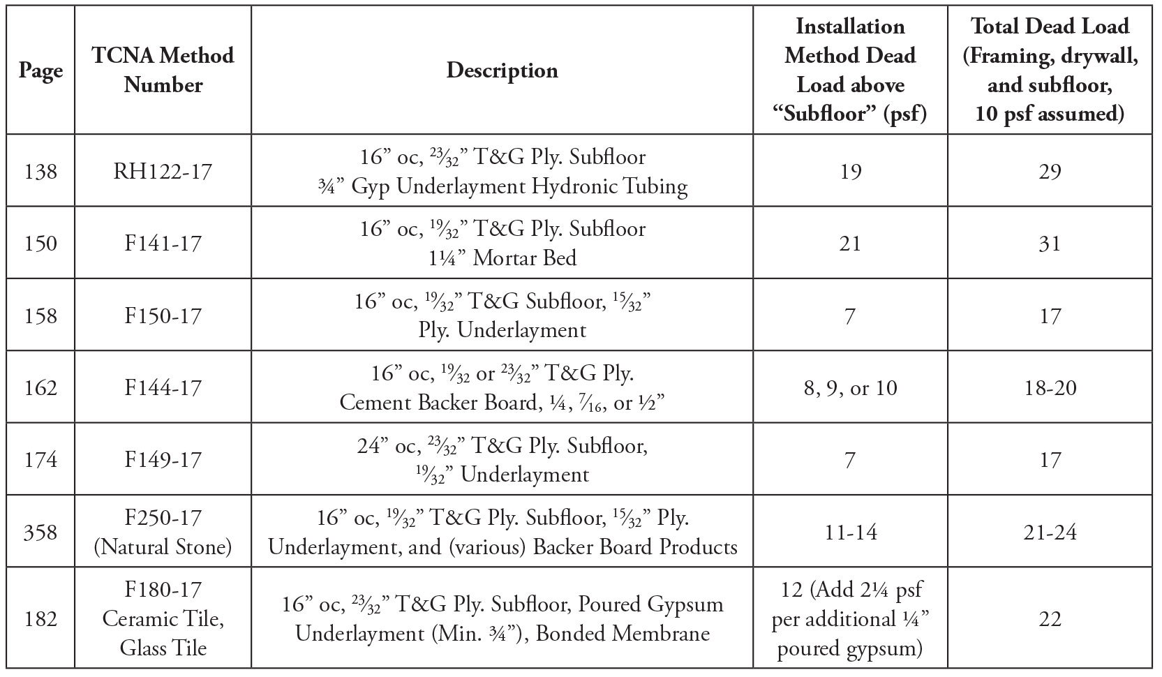
Table 1. Sample of Installation Methods from the 2017 TCNA Handbook.
In Table 1, the Installation Method Dead Load is the weight of the materials above the subfloor. Total Dead Load in the rightmost column is based on an assumed dead load of 10 psf for the subfloor, joist, and ceiling.
As shown in Table 1, a design dead load of 10 psf is not adequate when the floor covering is tile or stone. This structural issue requires the attention of all professionals involved in the specification of the hard surface/installation method, floor system design, and for framing inspectors.
An excerpt from the IRC, the International Residential Code, indicates that an inadequate assumed dead load could be a “code issue” with respect to maximum span (Figure 1) and, in addition, the extra loading can contribute to additional creep deflection that can result in tile, stone, and grout cracks.
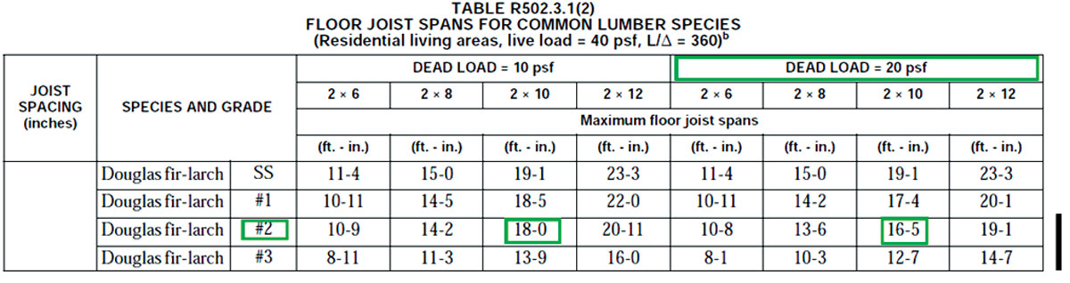
Figure 1. A portion of IRC Table R502.3.1(2).
The content of the IRC table suggests why the 2015 IRC span table for joists has two sections – one for an assumed dead load of 10 psf (carpet, vinyl, wood) and the other for a dead load of 20 psf (typical residential hard surfaces).
Tile Cracks
Tile cracks typically form on top of and parallel to the joist. The primary practical question is: With respect to floor design, what is more important for protecting tile or stone from potential cracking: joist deflection/stiffness (L/xxx) or floor sheathing thickness/stiffness? From engineering science for a beam (Bretzfield and Woeste, 2003),
1/ρ = M/EI
where ρ is the “radius of curvature” of the beam at the location of bending moment (M), and EI is joist stiffness.
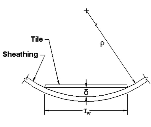
Figure 2. Depiction of stresses induced from the bending action of joists and sheathing/substrates.
To translate the expression, the amount of “bend” at any cross-section of a floor joist (or sheathing) span is proportional to the bending moment divided by the product of the modulus of elasticity (E) and moment of inertia (I) of the section. Referring to Figure 2 and the tile depicted, joists and subfloor/substrates with the largest possible ρ will minimize the stresses induced in the tile from bending action of the joists and sheathing/substrates, respectively.
Bend of Joists Verses Sheathing
Joist Bend Calculations
Using a total floor load of 60 psf, the authors calculated the radius of curvature, ρ, for several IRC joist spans at maximum bending moment. The results are given in Table 2.
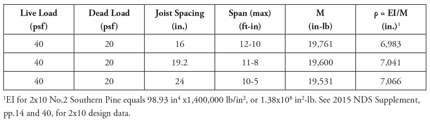
Table 2. Radius of curvature (ρ) for 2015 IRC maximum spans for 2×10 No. 2 Southern Pine joists and 40-20 psf loading (and L/360 live-load deflection limit).
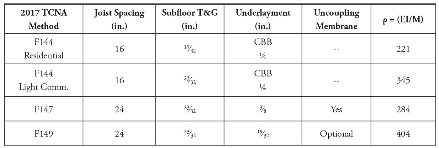
Table 3. Radius of curvature (ρ) for first sheathing span at maximum bending moment when loaded by a 300 lb concentrated load as applied in the ASTM C627 test of installation methods. (Note: For joists spaced 16 inches
on-center, M=927 in-lb; for joists spaced 24 inches on-center, M=1301 in-lb.)
The average radius of curvature for the joists is about 7,000 inches.
Sheathing Bend Calculations
The ASTM C627 standard for testing tile installation methods includes a rotating platform that applies up to 300 pounds at three locations (Figure 3).
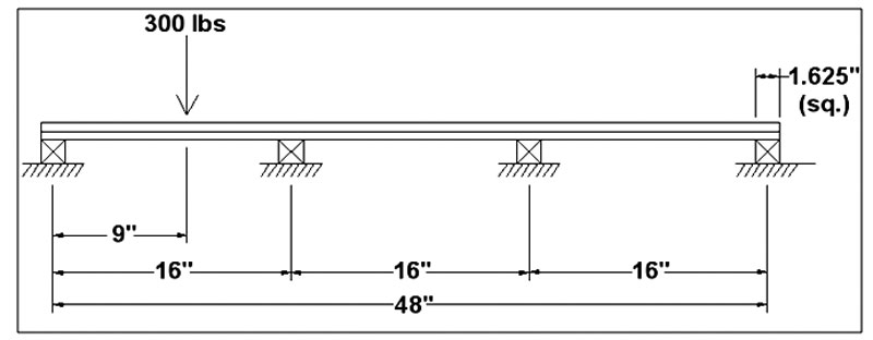
Figure 3. Cross-sectional view of the test specimen assembly of the Robinson-Type Floor Tester (ASTM C627).
The test does not include the deflection of the joists and butt joints in the subfloor and underlayment that are present in an actual construction. Likewise, the calculations below represent a best case scenario for an actual tile installation because a constructed floor contains joists that deflect under loads and the floor sheathing is butted at the 4- x 8-foot panel ends.
The authors calculated ρ for four (wood sheathing) installation methods using the following assumptions:
- A 300-pound concentrated load in the first sheathing span at the point of maximum moment, and
- No composite action between the subfloor and underlayment.
For the first wood sheathing span under a 300-pound concentrated load, ρ (calculated) for four TCNA Methods was about 300 inches.
The following statements summarize the relative importance of joist stiffness (L/xxx) versus sheathing stiffness.
- Floor sheathing bend, as determined by (1/ρ) under a concentrated load, is about 23X greater than the bend of the joist under 60 psf uniform live and dead load.
- Based on field evidence and engineering analyses (presented above), the structural designer for floor areas supporting tile or stone should place the greater emphasis on subfloor/sheathing specification relative to joist framing specifications.
- The analyses and recommendation as summarized above did not include the impact of end butt-joints in the subfloor and the impact of differential joist deflection due to concentrated loads, girders, and points of bearing that can cause differential deflections of framing.
Practical Specifications for Concentrated Floor Loads
For ceramic tile, the 2017 TCNA Handbook has “deflection requirements” listed for all framed floor system Installation Methods that cites the IRC and International Building Code (IBC), as well the following requirement:
“For ceramic tile installations, maximum allowable floor member live load and concentrated load deflection for framed floor systems shall not exceed L/360, where “L” is the clear span length of the supporting member per applicable building code.”
Given this language, uniform live load and concentrated load deflections in residential/multi-family applications are a requirement for the “supporting member” or floor framing system. The TCNA “concentrated load deflection” requirement is in addition to the requirements of the applicable IRC, as the authors are not aware of a concentrated dead-load deflection requirement in the 2015 IRC (or earlier editions). Knowing that concentrated loads such as kitchen islands may be shown on the Construction Documents, it is incumbent upon the design team to specify concentrated loads for the Component Manufacturer’s (CM) use (if trusses or I-joists are specified) or other measures to address the expected deflection from concentrated loads.

Figure 4. Kitchen island oriented parallel to the floor framing. For this case, almost the entire weight of the island would be supported by two framing members at 24 inches on-center.
An example of a modern and large kitchen island in residential construction is shown in Figure 4. The framing design question is – given the footprint of the island, what is a reasonable dead load specification?
The density of natural stone can vary between 160 and 200 lbs/ft2. As such, a stone thickness of 1¼ inches (30 mm) can weigh between 16.7 and 20.8 psf. Considering the weight of the cabinet, doors, and shelves, the island weight without contents approaches 30 psf (a sustained load).
The fact that it is a “sustained load” is significant, as sustained loads cause creep. Assuming the total dead load of the island with contents is 40 psf, it should not be considered equivalent to a 40 psf live-load due to creep deflection from sustained loads. Simply stated, an L/360 design based on a 40 psf live-load can experience additional creep deflection in-service due to a 40 psf “sustained load” with the actual joist deflection approaching L/180 (using a creep factor of 2.0 for trusses from ANSI/TPI 1-2014). For seasoned lumber, structural glued laminated timber, prefabricated wood I-Joists, or structural composite lumber used in dry service conditions, a creep factor of 1.5 is required.
Conclusions
The design of residential and multi-family floors has become more complicated due to the widespread use of hard surfaces and the placement of heavy items, such as large kitchen islands, in the center section of framing spans. When the uniform and concentrated loads, including creep deflection, are not adequately accounted for in the floor system design, in-service performance issues of the hard surfaces can be expected.
Based on analyses and experience, the following suggestions are offered for consideration by the design team.
- Prepare Construction Documents that contain:
a) the TCNA tile/stone Installation Method,
b) the weight of the installation method, and
c) the footprint and weight of kitchen islands (and other heavy equipment such as large front-loading washers). - Require floor system designs based on a “total load” that includes the actual weight of the TCNA Installation Method for the hard surface listed in the Construction Documents.
- Upgrade the subfloor thickness above the thickness specified for the TCNA Installation Method in the Construction Documents to improve the predicted bending behavior of the floor sheathing under a 300-pound concentrated load. (For example, a 23⁄32-inch T&G plywood panel has a bending stiffness (EI) of 320,000 (lbf-in.2/ft) when installed as a subfloor, whereas a 7⁄8-inch panel has an EI of 500,000 (lbf-in.2/ft). The EI of a 7⁄8-inch subfloor panel is 1.56 times greater than the EI of the 23⁄32-inch panel, thus providing substantially more protection for the hard surfaces.)
- Require strongback bracing for floor trusses to protect tile and stone floors against potential hard surface damage due to differential deflection of the joists (and to improve the likely vibrational performance of floors as well).
- Offer Customers (homebuyers and owners) floor framing and subfloor “upgrades” for added protection against the likelihood of tile and grout cracks and annoying floor vibrations.
Historically, the design rules in residential construction building codes addressed a concern for plaster cracking (L/360 live-load only deflection) and a floor collapse (40 live load plus 10 psf dead load) when solid-sawn joists and wood flooring were the norms. Fast-forward 100 years, longer joist spans, hard surfaces (ceramic, glass, and stone), and large kitchen islands are common, yet the current IRC does not include provisions to address the intrinsically inelastic nature of hard surface flooring. To do so, the design team must take into account concentrated floor loads and total load deflection to mitigate the serviceability issues that stem from the use of hard surface flooring. Hopefully, this article will motivate a coordinated effort by design teams to address serviceability issues for modern construction with hard surface flooring.■
A version of this article written for wood-framing/truss designers appeared in the June 2018 issue of The Component Manufacturing Advertiser.