
This is the second and final article in a two-part series highlighting the fabrication and erection of the building with a specific focus on the exposed structural steel. For general information about the project, please refer to the Part 1 article, which can be found in the August 2015 issue of STRUCTURE.
The new 105,000-square-foot Energy R & D building is complete. A grand opening ceremony was held in August 2017. This $45 million research facility houses physics and chemistry programs focused on energy technologies of the future. The building is a critical component in the development of Binghamton University’s science programs.
The extensive use of curved, round HSS members as a structural framing system and the primary visual components of the architecture is what makes this project unique. Building Information Modelling (BIM) was implemented extensively throughout the phases of design, detailing, and fabrication. Autodesk Revit was used to produce the Construction Documents, and SDS\2 software was used to model and detail the exposed HSS framing.
As noted in the first article, there are four structural systems in the building that utilize curved, round hollow structural steel (HSS): the Atrium Roof, the Link Rotunda, the Tree Stair, and the Canopies. These members served individually as the primary load-carrying components of their respective portions of the structure and are also combined into assemblies for trusses and frames.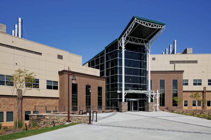
Detailing
Detailers at Schenectady Steel, the steel fabricator, built an SDS\2 model using the two-dimensional (2D) Construction Documents. Building the SDS\2 model from scratch allowed the detailers to get familiar with the complex geometry of the exposed structural systems and their components, and allowed the model to serve as a check on the accuracy and completeness of the Contract Documents.
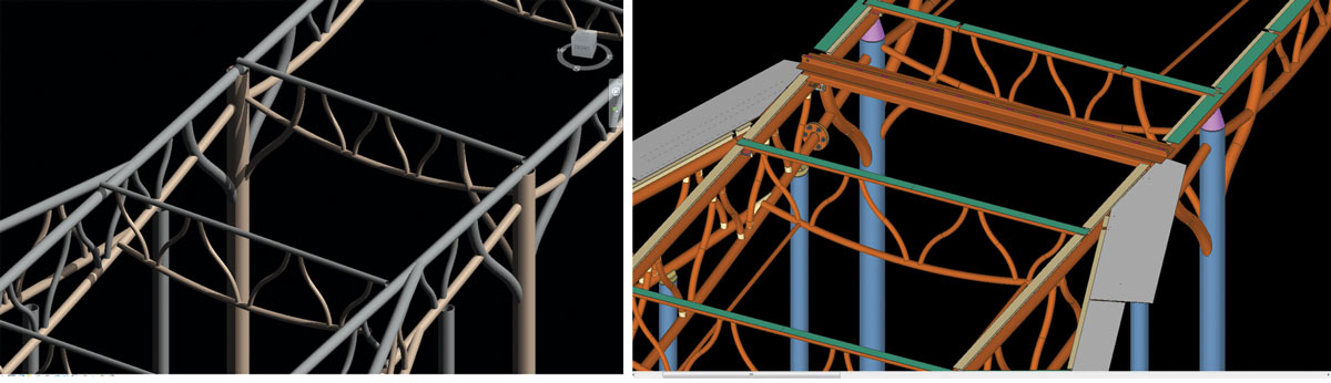
Figure 1. Revit and SDS2 renderings.
During design, the Revit model allowed for modeling of the structural shapes and geometry but did not accurately capture connection information or details at joints. This level of modeling represents a Level of Development (LOD) of 300. For LOD 300, each structural element is represented graphically in terms of quantity, size, shape, location, and orientation, and this information is sufficient in terms of producing 2D construction documents. The SDS\2 model developed by the fabricator captured all components needed for fabrication of the steel providing a higher LOD (400+). This more-detailed model included all of the individual parts and pieces that make up an assembly and showed how they fit together. Structural steel shop drawings showing final cut geometry were produced from this higher-LOD model. Information on LOD for BIM can be found in the BIM Forum’s specification. Figure 1 shows images from Revit and SDS\2 that illustrate the LOD difference.
Fabrication
Each component of the exposed structure utilizes a round HSS shape with a profile that has double curvature. A majority of the members consist of smaller sizes of round HSS for the truss webs, tree stair supports, and canopies. These could be cold bent in double curvature with a small and unnoticeable straight section at the inflection point. The larger, round HSS sections had to be bent in single curvature and then cut, rotated, and welded back together. These include the branch supports for the Rotunda and tree columns in the Atrium.
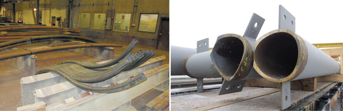
Figure 2. HSS prior to final cutting (left) and birds-mouth cuts (right).
The round HSS members were cold-bent by Oakley Steel Products in Bellwood, Illinois. Each piece was shipped to Schenectady Steel longer than required. The extra length was needed for overrun in order to fit the pieces into the machine that bends the steel and allows for final cutting and fitting during fabrication. Schenectady Steel then measured the steel and cut it to length with the appropriate birds-mouth profile (Figure 2). A majority of these profiles are unique since there are over 20 different truss arrangements and the curved web members have varying geometry with respect to the curved and sloped bottom chords. The actual cut geometry is fairly complex since most connection interfaces consist of a round shape coming into another round shape at an angle. The fabricator utilized templates that could be cut out and adhered to the steel so that the ironworkers could cut the birds-mouth shapes exactly. All of these templates were produced using the SDS\2 software.
The detailer developed a quality control program specific to the project for assembly of the trusses. This involved checking the physical material and laying out each component of the assembly to ensure it met the dimensional requirements of each truss. The shop drawings provided all of the work points and correct dimensions, but the actual pieces had to be assessed multiple times at numerous locations to ensure they met the geometry noted in the shop drawings. Parameters such as length, radius, and locations of inflection points of curves were measured for each member. There was minimal repetition in the truss size and geometry, which added to the required level of checking and double checking. Once checked, the next step was fitting them all together.
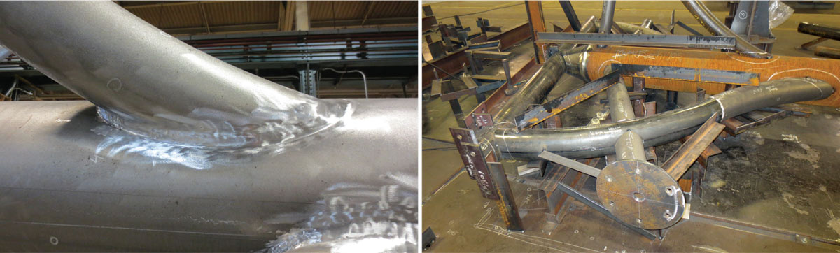
Figure 3. Ground welds (left) and jig for tree columns (right).
Fabrication of the round, curved steel required a lot of welding and grinding to make joints appear continuous, thereby concealing the actual weld. Some of the assembled shapes were unwieldy and required custom jigs to connect all of the components (Figure 3).
Fillet welding was used as much as possible, particularly at the truss web connections. The web geometry was laid out so that fillet welding could be used around the entire circumference of the webs in most locations. However, for members connecting at shallower angles, portions of the profile of the birds-mouths had to be prepared with a beveled edge; partial-penetration groove welding was used for those portions. Fillet welding was supplemented, where geometry allowed, to complete the all-around welds for each component.
Even with the printable templates, there was still plenty of fitting and touch-up work required for each assembly. The fabricator compared it to an elaborate and heavy pipe railing system due to the amount of grinding and birds-mouthing needed to assemble the individual components. Once the fabrication of each truss was complete, another round of finishing was conducted. This entailed further grinding and polishing of exposed welds to provide a genuinely uniform appearance.
The Rotunda, Tree Stair, and Canopies were mostly assembled in the shop and shipped to the site. Tops of branch members were welded in the field. The Atrium truss structure is more elaborate and required careful coordination to make sure each piece would fit in the field. An aggressive schedule added to the coordination effort since Schenectady Steel fabricated all of the trusses and JPW Structural Contracting, another steel fabricator based in Syracuse, New York, fabricated the tree columns that support the trusses. The girder trusses could not be test-fitted to the tree columns before erection at the site. However, Schenectady Steel did test-fit several purlin trusses to the girder trusses in the shop. The close coordination and rigorous quality control measures proved effective and made the erection process go smoothly.
Erection
The Contract Documents specified suggested locations of field splices for the Atrium, and the fabricator and erector generally followed those suggestions. The steel was erected with minimal shoring and temporary supports. Temporary seated connections were developed for the purlin trusses to allow for more rapid and safe erection and verification of acceptable field fit-up. The seats were made from steel pipe, one size larger than the truss chord, that was cut in half. Holes were then drilled to accommodate erection pins.
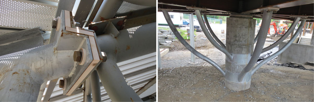
Figure 4. Thermally broken connections at rotunda and atrium.
As discussed in the first article, six of the ten Atrium tree columns are outside of the building envelope. Thermally broken connections, utilizing thermal isolation material (TIM), were used at the curtain walls to reduce thermal bridging. This technology was also used at the Rotunda structure since the lower branch members and concrete column are outside of the building (Figure 4).
Field connections for truss chord and branch members were made using complete penetration groove welds with backing. These welds are generally located where the members come together at an inflection point (straight portion of the member). The exposed sides of these welds were ground smooth to provide the appearance of a continuous structure. The fabricator and erector agreed on temporarily bolted tabs at these locations, which were later removed.
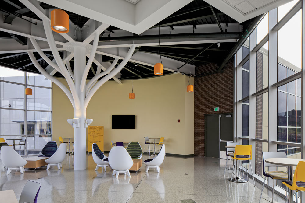
Figure 5. Rotunda first floor.
The Architect selected a dark green color for the exposed roof deck and conventional wide-flange roof framing and white for the curved HSS. This contrast, along with up-lighting on the columns, enhances the appearance of each space and each point of view of the structures. Figure 5 shows the final Link Rotunda structure as viewed from the first floor looking east. Figure 6 shows the final Tree Stair structure as viewed from the first floor looking west.
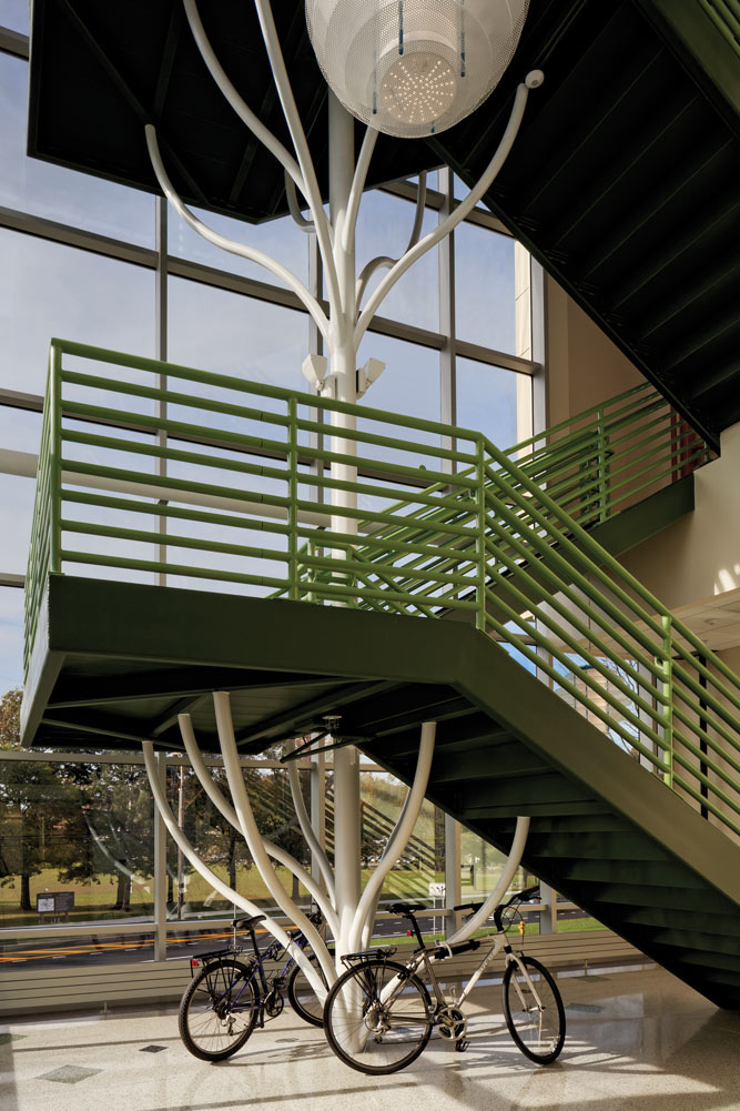
Figure 6. Tree stair.
The Energy R&D building is one of a kind. The exposed structure is the product of close collaboration between design professionals and contractors and is unique from both a visual and structural standpoint. Blending form and function was a key objective and was achieved in each component. The structure itself is more expensive than other systems but, as the primary architectural feature, it allowed for the elimination of a number of finishes that normally concealed a more functionally-driven system, thereby balancing the cost.
Each member of the team brought skill and ingenuity to the project, getting behind the concept from the very beginning. Overall, the Energy R&D building is one that invokes pride for those involved in its creation, and will serve as an important facility for Binghamton University now and in the future.
Special thanks to Robert Gennett of Schenectady Steel for contributing to this article.■
Project Team
Owner: Binghamton University, Binghamton, NY
Structural Engineers: Ryan Biggs | Clark Davis, Engineering and Surveying D.P.C., Skaneateles Falls, NY
Architect: William Hall, Binghamton University, Binghamton, NY
General Contractors: Fahs Construction Group, Binghamton, NY, and Andrew R. Mancini Associates, Inc., Endicott, NY
Structural Steel Fabricators: Schenectady Steel, Schenectady, NY, and JPW Structural, East Syracuse, NY
Photography: Architectural Photography & Design, Inc., Greene, NY