
Understanding and Minimizing Footfall Vibrations
Humans are restless creatures, always moving. They also tend to congregate and enjoy being restless together. Locate all this restlessness in just the wrong spot in a susceptible structure, and the structure is likely to join in – by vibrating in resonance. Structural amplification of human footfalls – walking, jogging, running, jumping, dancing – can be annoying at best and dangerous at worst.

Rendering of the New Boston College recreation center. Courtesy of CannonDesign, Inc.
Red Flags
Forces from human footfalls can produce unacceptable vibration for a variety of reasons. For example:
- The activity has a high fundamental frequency (relative to the range of human activity), like running
- The activity is rhythmic and synchronized, for example: aerobics
- The structure is particularly susceptible, as for a flexible, long span
- Spaces with different expectations are adjacent, as in offices next to a gymnasium
A large Boston College recreation center introduced challenges in all these areas. It also reflects two architectural trends that necessitate close consideration of vibration issues.
First, the design uses long, unsupported spans for gymnasium areas. In general, interior long spans are attractive because they permit more flexibility in space planning, better use of daylight, and better adaptability to future uses. In the Boston College structure, they provide an exceptionally large column-free space for sports. Such long-span, flexible structures are more likely to vibrate even under low-frequency forces such as those generated by footfalls.
Second, the center is a mixed-use facility with multipurpose workout spaces located near offices. The co-location of disparate activities in the same structure is central to trends in “live-work-play-eat-shop” development. The issue is that human tolerance of vibration depends strongly on context. In mixed-use structures, the tolerable level changes from one space to the next, but the vibration does not.
Key Concepts
Design for vibration must consider three things: the source, the transmission path, and the receptor – that is, the person, machine, instrument, or structural element affected by the vibration. Although that sequence reflects how vibration occurs, here it is useful to change the order and start with the receptor. After all, the receptor’s experience determines whether a design is successful.
Receptor: Perception
Usually, the goal of vibration control is human comfort but, in some cases, design centers on the performance of sensitive equipment. The focus here will be on humans, but many of the same concepts apply to other receptors.
Human perception of vibration depends on three factors. The first two are frequency and amplitude, which are perceived physiologically. The third is usage or context, which crucially determines how vibration is perceived psychologically. The degree to which people will tolerate vibration varies significantly depending on circumstance: location (on the street, in the gym, in the office, in the home), time of day (morning, evening), duration (seconds or hours), and so on.
![Figure 1. Criteria for peak acceleration in floor vibration. The acceleration depends on the fundamental frequency of response of the floor. (Adapted from American Institute of Steel Construction [AISC])](https://www.structuremag.org/wp-content/uploads/2018/10/1118-sa-1.jpg)
Figure 1. Criteria for peak acceleration in floor vibration. The acceleration depends on the fundamental frequency of response of the floor. (Adapted from American Institute of Steel Construction [AISC])
First, the y-axis: how much the structure moves. Here is the first source of confusion: The y-axis quantifies amplitude not as displacement but as peak acceleration. To see why acceleration works as a stand-in for amplitude, consider two structures moving at the same frequency or, equivalently, taking the same time for one cycle but at different amplitudes. The structure that travels through a greater amplitude must move faster to cover more distance in the same time. It thus experiences greater acceleration when the structure’s motion changes direction.
Second, the x-axis: frequency. Here the axis measure is not complicated, but the human response is. Usually, extreme stimuli evoke extreme responses. For vibration, counterintuitively, the upturn at both ends of the curve shows that we are less sensitive at the extremes of frequency. For example, consider the left endpoint of the top curve. It means that someone in an outdoor context could tolerate vibration at 10% g (where g is gravitational acceleration) and 1 Hz – equivalent to someone walking slowly (or jumping) on a lively outdoor footbridge. However, if the motion were at 4 Hz – perhaps equivalent to someone running on the footbridge – a person could tolerate a vibration of only 5% g.
The bottom curve needs further clarification: It is the threshold of perceptibility. Below this level, vibration is not perceived. (Note that it uses a slightly different measure: the root mean square [RMS] acceleration.)
Source
The critical feature to know about the source is its frequency content. Various types of frequency analysis can be used. Footfall forces are usually low frequency:
- Walking: 1.5 – 2.2 Hz
- Running: 2 – 4 Hz
- Descending stairs: 1 – 4.5 Hz
- Synchronized crowd bobbing: 1 – 3 Hz
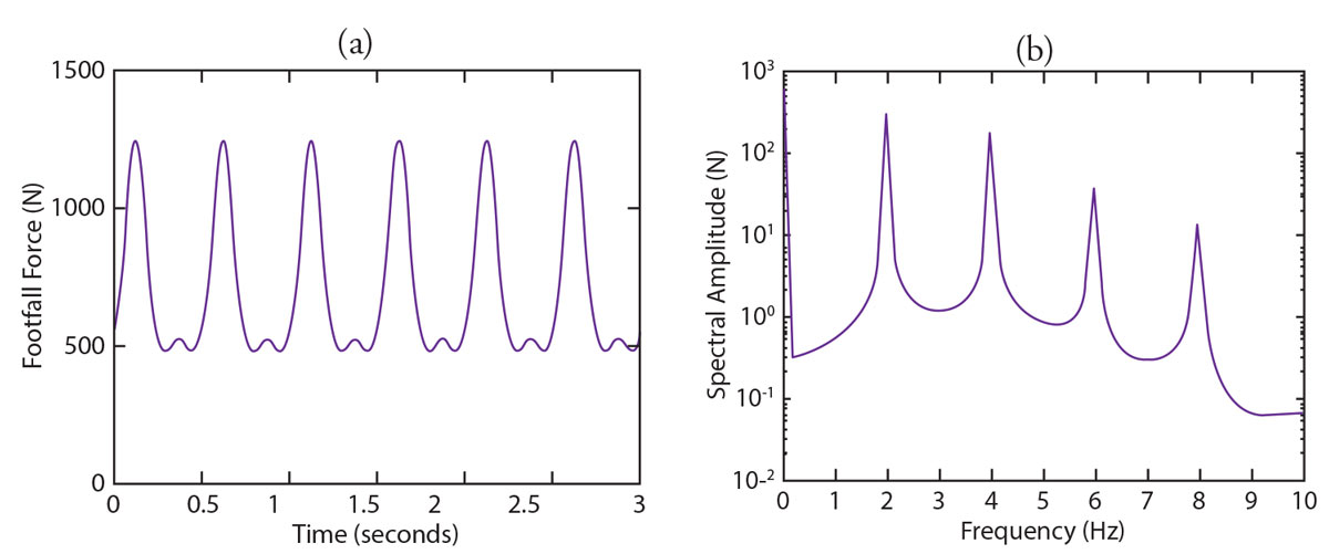
Figure 2. a) Typical footfall force; b) harmonics for someone walking at about 2 steps per second.
Both the fundamental walking frequency (Figure 2a) and higher harmonics (Figure 2b) should be considered, but harmonics are usually of less concern, as discussed in the next section.
Models of the cumulative force of footfalls include assumptions about the frequency of the activity, the size of any groups, and the locations of the individuals or groups.
Transmission Path
How a dynamic system responds to the forces of vibration will depend on the characteristics of the system’s transmission path: its mass, stiffness (restoring force), and damping (energy dissipation).
Every oscillator has a frequency at which it responds more strongly: its natural frequency. When the forcing frequency is near the natural frequency, the effect is resonance: the oscillation is amplified. When the system has no way to dissipate the incoming vibrational energy – that is, it has low damping – the result will be a large resonant response.
The primary issue for occupant comfort occurs when the fundamental frequency of the activity (Figure 2a) aligns with the natural frequency of the floor. The higher harmonics can also excite the structure, but they are a lesser concern because they have lower amplitude and thus carry less energy; floors also tend to be less responsive at these higher frequencies.
RWDI models flooring systems using methods based on those recommended by the Steel Construction Institute (P354) and Concrete Center (CCIP-106). Because the models are based on finite element methods, loading and response can be determined for any point on the floor; in addition, multiple vibration modes can be investigated.
An essential aspect of evaluating the results is the frame of reference. The response of a structure can be modeled and quantified in several ways: for example, peak-to-peak response, one-third octave frequency response (which uses “bins” to group higher frequencies), narrow-band frequency response, and root mean square (RMS) acceleration. Because the data are being processed differently in each of these frames of reference, the magnitude of response will be different. Thus, when evaluating whether the structure’s response exceeds criteria, the criteria and the response data must be from the same frame of reference. Response data in the time domain can be converted to any frame of reference.
Mitigation
Strategies for mitigating vibration issues can be architectural or structural. Architectural mitigations might involve moving the receptors (e.g., offices) or moving walking paths or activity locations. Structural changes might involve using heavier floors, stiffer beams, interstitial posts, or supplementary damping.
Human tolerance of vibration depends on frequency, with higher tolerance at the extremes of frequency. Thus, a key to structural mitigation is to use the floor to filter vibration at the right frequency. That is, the floor can be “tuned” to be less responsive at the forcing frequency. The effectiveness of this strategy depends on where the forcing frequency falls on the floor’s response curve, as shown in Figure 3.
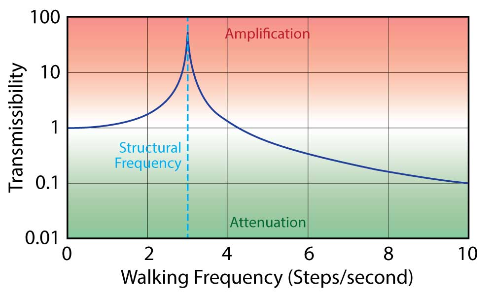
Figure 3. Relation of floor response and forcing frequency. This floor would amplify footfall vibration from running (2 – 4 Hz). A transmissibility of 1 means the floor transmits the vibration force perfectly, without amplification or attenuation. Vibration can be mitigated by tuning a floor’s natural frequency away from the forcing frequency.
One such solution is a floating floor – with a caveat. This type of floor is given a fundamental frequency much lower than the source so that it acts as an isolator at higher frequencies. Floating floors are used very successfully for machinery, but typical floors intended for that application do not work well for human activities because they are not designed to isolate low frequencies. However, floating floors can be custom designed to the appropriate frequencies, e.g., for fitness centers.
Another very common proposal is resilient flooring. It is entirely ineffective. Such flooring is usually designed to minimize impact force on joints, so people are not injured while exercising. Resilient flooring does not filter at the right frequencies to prevent floor vibration.
When significant additional damping is needed and cannot be achieved by other structural means, one solution is to add a mechanical damping system. An advantage of such systems is that they can be precisely tuned to the needed frequency.
Case Study
The purpose of vibration analysis is to determine whether the frequency of the source will provoke a resonant response in the structure. The steps in a vibration analysis are:
- Identify the frequency characteristics and forces of the source
- Model the vibration modes of the structure
- Evaluate the structure’s response at the source frequencies, including source harmonics
- Compare the response to the tolerance criteria, using criteria matching the frame of reference used for response
- Model response with mitigation solutions in place
RWDI undertook this type of analysis for a recreation center designed by CannonDesign for Boston College, Newton, Massachusetts. The four-story, 244,000-square-foot structure will provide four basketball courts, three tennis courts, swimming pools, two multiactivity courts, and multipurpose rooms for yoga, spin, and other fitness classes. Construction began in spring 2017 and is expected to be complete by summer 2019.
CannonDesign requested a review of vibration issues because of a combination of two features:
- Two unusually long unsupported spans:
a) A tennis court gym at 115 feet by 137 feet (35 meters by 42 meters)
b) A four-court basketball gym with suspended track at 107 feet by 161 feet (33 meters x 49 meters) - A concrete-on-concrete floor system for these spans, using precast double tees placed on a precast bent
These spans are much larger than the typical concrete span of 30 feet by 30 feet (9 meters by 9 meters). The concrete floor system is not unusual but, for transmission of vibration, concrete-on-concrete joints behave differently than more conventional concrete-on-steel structures.
These structural choices were made because a multistory design was necessary to accommodate the desired program within a constrained site. The designers explored structural systems to minimize structural depths and maximize usable volumes of space for activities. Post-tension precast concrete bents provided both the shallowest depth and the structural capabilities necessary for the stacked program, as well as an aesthetic complementary to the Collegiate Gothic style.
RWDI was asked to evaluate three scenarios:
- Use of tennis court gymnasium (unsupported span)
- Use of four-court basketball/running gymnasium (unsupported span)
- Use of a multipurpose exercise space adjacent to offices, located in the tennis court gymnasium
Figure 4 shows the concrete system under construction, and Figure 5 shows the finite element model of the four-court basketball gymnasium.
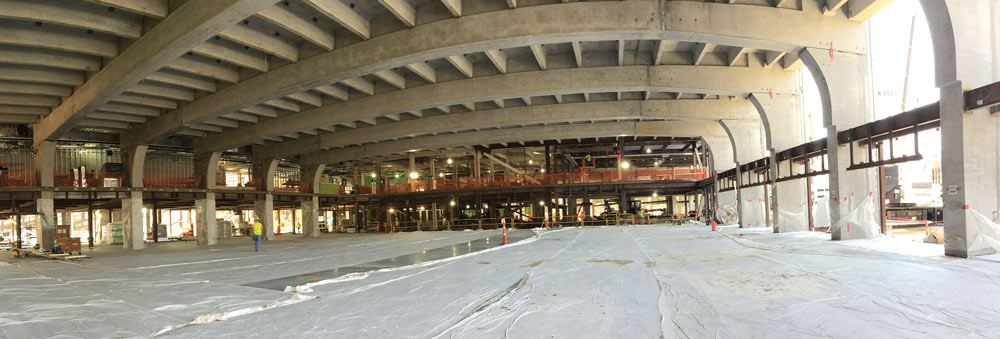
Figure 4. Long-span concrete flooring system under construction, showing precast double tees placed on a precast bent. Courtesy CannonDesign, Inc.
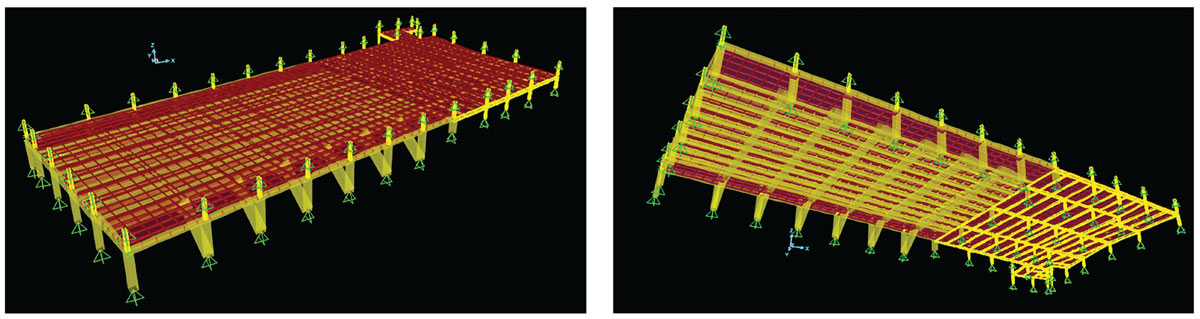
Figure 4. Long-span concrete flooring system under construction, showing precast double tees placed on a precast bent. Courtesy CannonDesign, Inc.
Concrete does not introduce any issues as a transmission medium. However, the presence of concrete-on-concrete interfaces does require adjustments to the calculations. Such interfaces will deteriorate differently than typical concrete-and-steel interfaces. Cracked concrete usually acts as a solid member because the friction between the elements holds it together. Here, the beams are expected to deteriorate by crumbling at the edges, leaving a gap between a tee and the beam on which it rests. The model was adjusted by treating the beams as pin-connected instead of continuous.
Another adjustment was in the selection of loading scenarios. Standard occupancy loading was not appropriate; instead, the model had to account for concurrent uses by distinct groups engaged in different activities (running vs. basketball). Experience with smaller scale fitness centers helped in selecting scenarios to consider. Several typical scenarios were identified – for example, unsynchronized runners on the track. The model was used to calculate two figures: 1) the floor stiffness required to meet criteria under these typical scenarios, and 2) at that stiffness, the number of people who could participate without exceeding the criteria.
Figure 6 shows an example of the response mapping. The results were unexpected. The designers were concerned about potential issues in the gymnasium areas, but the only location to exceed criteria was somewhere else entirely: a multipurpose space adjacent to offices, in an area with conventional construction. If 50 people were to perform synchronized aerobics in the multipurpose space, the vibration in the office space could exceed the criterion for offices.
The reason for this result is relative mass. In the gym, runners are a very small mass exciting a much more massive structure; even a very flexible structure will not respond much. In the multiuse room, even though the space is much stiffer, more mass (50 people) is exciting a smaller area.
Because of the unconventional flooring strategy, the project structural engineer was required to include performance specifications in the design document. A similar vibration analysis was performed for the general contractor to demonstrate that subsequent modifications meet the performance specifications.
Keeping Restless People Happy
Generally, a building that has vibration problems is likely always to have vibration problems. Once built into a structure, such issues are among the most difficult to address through retrofits. Thus, extra advanced scrutiny in the following cases will be well rewarded by a higher performance structure.
- Long, flexible structures are most likely to show an undesirable response to human movement.
- Mitigation efforts are best focused on removing vibration response in the 4 to 8 Hz range, where human tolerance is lowest.
- Special consideration must be given when people in adjacent spaces will have different expectations. Vibration does not respect the boundaries of building programs.
By being alert to these critical scenarios, designers and engineers can help ensure that people can enjoy their ceaseless activity without having it bounced back at them – or at their neighbors.■
Project Team
Owner: Trustees of Boston College, Chestnut Hill, MA
Structural Engineer of Record: CannonDesign, Inc., Boston, MA
Specialty Structural Engineer (precast concrete bents) and Design Manager: Blue Ridge Design Inc., Winchester, VA
Architect of Record: Cannon Design, Inc., Boston, MA
Construction Manager: Skanska USA, Boston, MA
References
TM Murray, DE Allen, EE Ungar, DB Davis (2016). “Vibration of Steel-Framed Structural Systems Due to Human Activity, 2nd Edition.” American Institute of Steel Construction (AISC) Design Guide 11.
AL Smith, SJ Hicks, PJ Devine (2009). “Design of Floors for Vibration: A New Approach.” The Steel Construction Institute (SCI) P354.
MR Willford, P Young (2006). “A Design Guide for Footfall Induced Vibration of Structures.” The Concrete Centre CCIP – 016.