
Utica, New York 1873
The Hotel Street Lift Bridge, constructed in Utica, New York, in 1873, was a first of its kind and a gateway to long-span lift bridges in later years. In the 1850s, the Erie Canal Board adopted Whipple bowstring trusses (STRUCTURE, January 2015) to cross the canal in cities requiring a span of 72 feet, as that was the standard span for the Whipple bowstring. The enlarged Erie Canal, in the countryside, was 72 feet wide at the surface with a 10-foot towpath. In cities requiring a lesser span of 60 feet wide, vertical masonry walls were typically used with a 10-foot towpath. In the scenario, the towpath was at the street level of all of the city streets the canal crossed. However, when a Whipple bowstring truss was used to allow for a 72-foot span, the trusses had to be raised accordingly to provide clearance between the bottom of the truss and the mules/horses pulling the canal boats. Therefore, with a deck level about 11 feet above the towpath, the city street was required to be sloped up to the bridge. Since there is a limit on the grade a team of horses can pull a loaded wagon up, longer slopes were required. The required fill infringed on businesses along the streets. On a few occasions, the Board adopted side mounted swing bridges; however, when in an open position, they took up valuable frontage along the canal. Whipple designed side mounted iron swing bridges across the Erie and the Louisville and Portland Canals, as well as wood and iron swing bridges across the Welland and Dundas Canals in Canada.
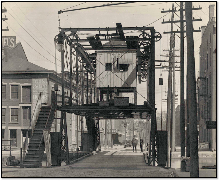
Hotel street bridge after reconstruction.
Given some unique challenges at the location, Whipple was asked by state officials to determine the feasibility of a lift bridge at Hotel Street in Utica to eliminate the high fills. Whipple described the situation as follows,
In 1871 the Legislature of New York passed an act authorizing the construction of a swing-bridge over the Erie Canal on Hotel Street in Utica, for the purpose of enabling heavy loads to cross the canal without encountering the steep grades by which the stationary bridges of the city are necessarily approached. But the canal being only 59 feet wide at that point, a pier in the centre was inadmissible, while a bridge mounted on a pier upon the shore, would be so long, and occupy so much room when open, that it could not be constructed and used without the abatement of one or more valuable business stands. This would have involved an amount of expense, which neither the state authorities nor the citizens to be benefited by the bridge were willing to incur.
In this condition of the case, the writer was consulted as to the practicability of devising a plan of draw-bridge which could be operated by lifting up instead of swinging horizontally, whereby the anticipated benefits could be enjoyed without incurring so much expense, and occupying so much valuable space. The idea at once struck me as highly feasible, and the suggestion was answered accordingly.
In pursuance therewith, the plan of a “lift draw-bridge” was arranged, for which letters patent were issued about two years ago. The plan being thought favorably of by parties concerned, an appropriation was made in 1873 for the construction of such a bridge at the locality above named, and a contract entered into therefore.
After some study, Whipple applied for and obtained a patent and was granted it December 24, 1872 (patent #134388). He began his application with,
This improvement is especially applicable upon navigable canals through cities and villages, as it occupies much less space and requires less time in operating it than is required for the pivot or swing draw-bridge. No claim is here made to the original invention of lift draw-bridges in general, or of any particular plan for the stationary trusses, or of any particular mode or arrangement of or applying the winding power to the winding drum, m, in case it be used, or the working power to the transverse shaft, f, in case of the power weight being dispensed with… I do claim as my invention, and as not before known or used,
- In the construction of lift draw-bridges, the combination of the counterpoised vertical movable way or platform, the trusses, the suspension rods, chains, or ropes, the longitudinal shafts on each side of the bridge, and the transverse shaft or shafts and gearing, substantially as and for the purposes specified.
- The longitudinal and transverse shafts connected by gearing to effect the simultaneous rotation of the shafts and a uniform vertical movement of all parts of the platform, substantially as specified.
- The combination of the power-weight and winding-drum, m, upon the transverse shaft for the purpose of working the draw, substantially as set forth.

Lift bridge patent drawing.
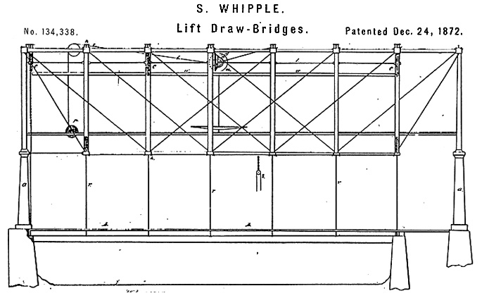
As can be seen, he had taken his Whipple double-intersection trusses (STRUCTURE, November 2014) in the orientation they would have had if the bridge was being used as a deck truss and supported them on four cast-iron columns. In his own words:
The work consists of a stationary truss bridge spanning both the water-way and towing-path supported by 4 corner piers and towers, sufficiently high for the suspension of a movable floor or platform under the lower truss-chords and to permit the passage of canal boats underneath the platform-together with other parts about to be named and described.
The movable platform, extending from the berm bank to the inner edge of the towing path, is suspended by iron suspension rods (one at each end of each transverse floor-beam) passing up through the cast iron connecting pins of truss chords and inside of the hollow truss posts, being connected at the upper ends with wire rope passing over large sheaves or pulley-wheels, and connecting with counterpoise weights to balance the weight of the platform…
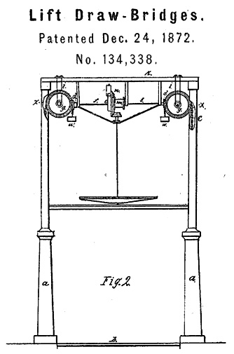
Patent drawing showing lift mechanism and treadwheel.
He described the lift mechanism as follows:
The platform being thus mounted and counterpoised, is lowered to the grade of the street for the passage of land vehicles and raised for the passage of boats underneath, by application to the transverse shaft of power sufficient to overcome the friction of the working parts, with a greater or less surplus to act as an acceleration force…
The counterpoise weights consist of 12 cast-iron boxes (6 upon each side), 9 inches square, with length corresponding to the length of truss panels, weighing about 800 pounds each, and containing about a like amount of pig-iron…
For winding up, the plan adopted was a tread-wheel, 9 feet in diameter upon a vertical shaft, with a bevel pinion working into gear segments attached to the winding-drums, which run loose upon the transverse shaft in winding, and in running down operate by means of a dog or catch and a ratchet wheel made fast to the shaft, essentially in the manner of the working of a clock propelled by a weight…
In conclusion, I will only remark that this plan of draw-bridge (applicable to railroad or common street purpose) is, of course, solely adapted to canal navigation, where boats require a head-room of 12 or 14 feet in height only; and for such use it seems clearly to possess the following advantages over other plans:
- It does not obstruct the navigable channel like a swing-bridge on a pier in the centre of the canal.
- It occupies much less space than a swing bridge mounted upon a shore pier and is less seriously affected by the action of wind.
- It is considerably less expensive in construction; and
- It is more easily managed and worked than any other canal draw-bridge, except possibly the swing-bridge, with centre pier and narrow boat-channels on either side.
With this design, the deck of the bridge when in a down position was on the same level as the towpath and crossing street. When in the up position, it provided 12 feet of clearance for the canal boats and mules. With Whipple’s plan and patent in hand, the state passed Chapter 766 of the Laws of 1873 authorizing the construction of a lift bridge at Hotel Street in Utica. On August 20, 1873, a contract was signed for the construction of “A Whipple Patent Draw (or lift) Bridge over the Erie Canal at the City of Utica in accordance with the provisions of Act Chapter 766 Laws of 1873.” The contract price was $100 per foot for the bridge superstructure, and the work was to be completed on or before January 1, 1874. The hand-written specifications attached read, in part, as follows,
The trusses to be of wrought and cast iron, proportioned according to the specification adopted by the Canal Department for the Construction of the Whipple Trapezoidal Truss Bridges; and connected at both upper and lower chords by seven inch wrought iron I beams weighing 20 lbs. to the lineal foot, extending from truss to truss, with suitable end connections.
The trusses so formed and connected are to be supported by four hollow iron towers or pillars, thirty inches in diameter at the base, ten inches at the top and twelve feet high with suitable cap pieces to receive and support the ends of trusses. These towers are to stand upon the stone foundation herein specified…
The bridge is to be provided with a suitable and convenient stage or platform to be occupied by the operator while attending and working the bridge with convenient means of access thereto; and decking covered with tin to protect him from storms covering the whole width of the bridge and not less than twelve feet of its length in the central portion thereof.
The Utica Morning Herald of September 16, 1873, reported, “the structure will be new in design, being the first one of its kind ever put up. The inventor is the well-known bridge builder, Squire Whipple. He has obtained letters of patent for the design, and engineers are awaiting the results of the test here to put up the same kind of bridge elsewhere should it prove successful in Utica… The whole mechanism is so simple that any blacksmith can repair it when out of order… The cost of the bridge outside of pier work and incidentals will be about $10,000.” He built the bridge in partnership with S. W. Chubbuck, who ran a foundry on upper Whitesboro Street. The bridge opened on time and within budget. On September 14, 1883, just less than 10 years after it was opened, the bridge was destroyed by a canal boat carrying a large load of lumber. The Utica Morning Herald wrote,
The bridge tenders are Alexander C. Jones and George Butts. They saw a boat approaching from the west and attempted to lift the bridge as usual. The machinery of the bridge would not operate, and the roadway did not stir. The captain of the boat saw the dilemma of the men and attempted to stop his boat which had on a heavy load of lumber…The boat which was moving slowly touched the bridge and in less time than it takes to write it, pushed it from its foundation, and it toppled over into the canal a total wreck. The roadway which is in the canal is probably uninjured, but the supporting cast iron pillars which formed the upper part of the bridge, the framework piers which support the entire weight, the stair approaches and iron rail were completely demolished and will be of value only as scrap iron. The wire cables on which the bridge hung are twisted, and the whole is about as bad a wreck as was ever seen anywhere. It lies in the bottom of the canal, completely obstructing navigation.
The bridge, however, was rebuilt using latticed wrought iron angles for the four cast iron pillars. Most of the operating mechanism was salvaged and placed back into the structure. Fixed stairs and a walkway were added to permit pedestrians to cross the canal when the span was in an up position.
Thirty-one years later, the Utica Sunday Tribune of September 20, 1914, printed an article on the front page entitled “An Antiquated Bridge Lifted by Leg Power.” It read in part,
One of the queerest and most obsolete bridges along the whole course of the Erie Canal is at Hotel street in the very heart of Utica. The thousands of persons who see it or pass over it every day are so accustomed to this relic that they seldom, if ever, think of the ancient form. A few hundred feet further west, at Seneca Street, is an ultramodern bridge, in which the operator has but to move a lever and electricity raises or lowers the huge platform. But at Hotel street, men still furnish the power to raise and lower the bridge by means of a treadmill on which they walk, like a dog turning an old-fashioned churn.
The bridge served until 1921 when it was taken down as the canal was filled in. The Utica Saturday Globe of March 12, 1921, ran a picture of the bridge and the adjacent John Street lift bridge, along with an article entitled “Those Bridges-Hotel and John Street [also a lift bridge but not a Whipple] Structures Soon to Be a Memory.” The bridges were gone by the end of the month.
With the construction of this bridge, probably the most complex structure he had designed and built since his weigh-lock scales at Utica in 1841, Whipple had, from his semi-retirement in Albany, pointed the way to the long-span lift bridges of J. A. L. Waddell that were later built around the country starting in Chicago in 1894.▪