
In 2015 and early 2016, the American Iron and Steel Institute (AISI) published AISI S400-15/S1-16, North American Standard for Seismic Design of Cold-Formed Steel Structural Systems with Supplement 1. This first edition of AISI S400 represents a merging of the following previously published standards:
- AISI S213, North American Standard for Cold-Formed Steel Framing-Lateral Design, a standard for the design of cold-formed steel frame shear walls, strap-braced walls, and diaphragms; and
- AISI S110, Standard for Seismic Design of Cold-Formed Steel Structural Systems – Special Bolted Moment Frames, a standard for the design of cold-formed steel special-bolted moment frames.
This consolidated seismic design standard brings together all North American cold-formed steel seismic-force-resisting systems (SFRS) into one standard, adding a consistent capacity-based design philosophy to each. It provides U.S.-based requirements for buildings located in Seismic Design Categories D and E, and for buildings located in Seismic Design Categories B and C when the chosen seismic response modification factor, R, as specified in ASCE 7-16, is taken as other than 3. The standard also provides Canadian seismic design provisions where the seismic force modification factors, RdRo, are taken as greater than or equal to 1.56, or the design spectral response acceleration S(0.2), as specified in the National Building Code of Canada (NBCC), is greater than 0.12.
Chapter A, Scope and Applicability
This standard focuses on the design and construction of cold-formed steel members and connections in seismic-force-resisting systems (SFRS) and diaphragms in buildings and other structures. It is intended to be used in conjunction with AISI S100, AISI S240, and the applicable building code. In the absence of an applicable building code, the design requirements must follow accepted engineering practice for the location under consideration, as specified by ASCE 7-16. The standard is not applicable in Seismic Design Category (SDC) A; or, SDC B or C when the chosen seismic response modification coefficient, R, equals 3.
Chapter A also provides the provisions for determining the material expected strength for steel. Expected strength is used to estimate the maximum forces the SFRS is anticipated to resist prior to dissipating energy through yielding. In earlier standards, this concept was described as the “maximum force the system can deliver.” The standard specifies both the expected yield stress and the expected tensile strength as:
Expected yield stress: Fy_expected = RyFy
Expected tensile strength: Fu_expected = RtFu
Ry and Rt are provided in AISI S400 Table A3.2-1.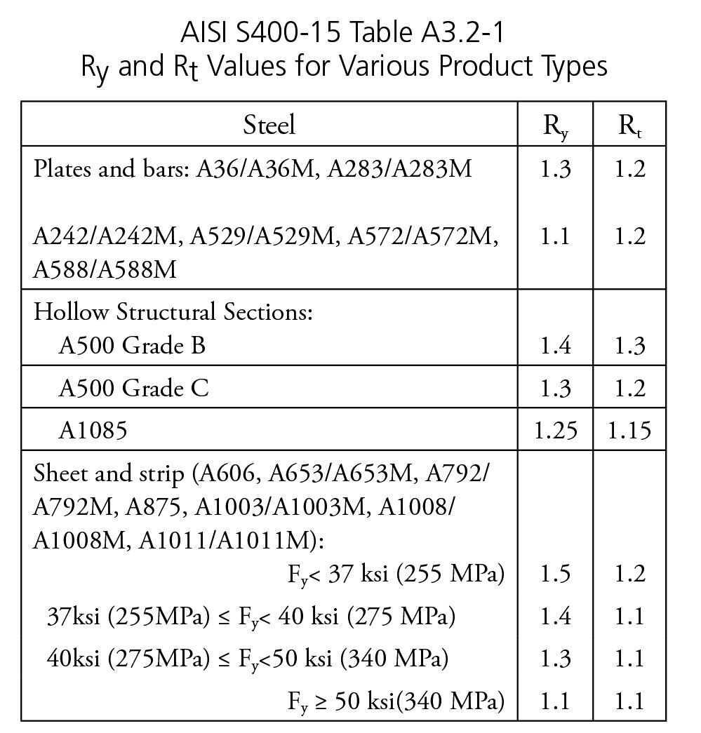
Unique to cold-formed steel, an additional yield stress increase must be considered due to the cold work of forming and inelastic reserve capacity:
- The modification coefficient for strength increase due to cold work of forming is determined as:
Rcf = Fya/Fy ≥ 1.1
Fya = average yield stress considering corner strength increase
Fya can be determined using AISI S100
- The modification coefficient for inelastic reserve capacity for the fully effective section in bending is calculated as:
Rre = Mn/My For λ < 0.673 (Eqn. A3.2.3)
Rre = 1 For λ ≥ 0.673
where Mn and My = nominal moment capacity considering inelastic reserve capacity and yield moment, respectively, determined in accordance with AISI S100.
Chapter B
This chapter, General Design Requirements, outlines fundamental seismic design requirements. Specifically, the available strength of the SFRS must be greater than or equal to the required strength determined from the applicable load combinations to ensure adequate performance in a design-level seismic-event. The required strength for structural members and connections in the lateral-force-resisting system, which is not part of the designated energy-dissipating mechanism, is determined from the expected strength of the SFRS; however, it does not need to exceed the seismic load effects determined in accordance with the applicable building code, where the seismic load effects include overstrength (Ωo).
The designated energy dissipating mechanism and methods for determining the expected strength of the various SFRS are included in Chapter E, as discussed below.
Chapter C
This chapter, Analysis, prescribes that the structural analysis should be done in accordance with the applicable building code and AISI S100. Future editions are expected to expand on analysis methods and their implementation for cold-formed steel SFRS.
Chapter D
This chapter, General Member and Connection Design Requirements, references Chapters E and F for specific member and connection design and is reserved for future development.
Chapter E
In this chapter, Seismic Force-Resisting Systems, U.S. design provisions for the following cold-formed steel SFRS are provided:
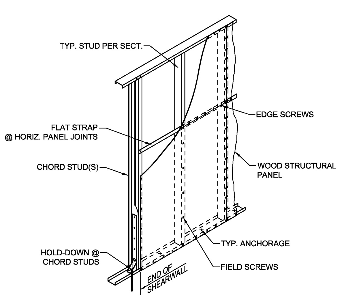
Figure 1. Shear wall sheathed with wood structural panels.
(a) Cold-formed steel light frame shear walls sheathed with wood structural panels SFRS (Figure 1): Seismic energy is dissipated in wood structural panel shear walls through titling and bearing deformation in the screw connections between the wood structural panel sheathing and the cold-formed steel structural members, and in the wood structural panels themselves. Two types of shear walls are included within the section:
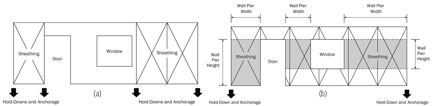
Figure 2. Sheathed shear wall analysis models. a) Type I shear walls (without detailing for force transfer around openings); b) Typical Type II shear wall.
Type I shear walls (Figure 2a) are fully sheathed and require hold-downs and anchorage at each end of the shear wall. If an opening exists, details must be provided for load transfer around the opening. The nominal shear strength for 15⁄32-inch structural 1 sheathing and for 7⁄16 OSB shear walls with a variety of fastener spacings and framing thickness are tabulated. Aspect ratio (shear wall height, h, divided by length, w) limits for the various assemblies are also provided.
Type II shear walls (Figure 2b) permit openings in the wall without specific design for force transfer around the openings. The nominal shear strength, Vn, can be determined:
Vn = CavnΣLi (AISI S400 Eqn. E1.3.1.2-1)
where vn = nominal shear strength per unit length; Ca = shear wall adjustment factor; Li = the total length of Type II shear wall segments that are sheathed full height. The nominal shear strength per unit length, vn, is based on the values for Type I shear walls and Ca is tabulated in the standard for a variety of shear wall geometries.
The expected strength of the SFRS, capped by the seismic load effects including overstrength, is to be used to design other components in the SFRS that are not part of the designated energy-dissipating mechanism, including any collectors. For this SFRS, the expected strength equals 1.8 times the nominal strength of the SFRS.
To ensure the shear wall performs as intended, additional system requirements must be met as further detailed in AISI S400, Section E1.
(b) Cold-formed steel light frame shear walls with steel sheet sheathing SFRS: Seismic energy is dissipated through the connections between the steel sheet and the cold-formed steel structural members. Yielding also occurs in the tension fields across the steel sheet. The nominal shear strength, Vn, can be determined using the same equations provided in Section (a) except that values for vn and Ca are tabulated separately in the standard. In addition, a new effective strip method has been introduced in this edition, which can be used to determine the nominal shear strength of the shear wall analytically.
The expected strength of steel-sheet sheathed shear walls is specified as 1.8 times the nominal strength of the SFRS.
To ensure the shear wall performs as intended, additional system requirements must be met as further detailed in AISI S400, Section E2.
(c) Cold-formed steel light frame strap braced wall systems SFRS: To perform as intended in a design level seismic event, this common SFRS must be designed and detailed to ensure that the diagonal tension strap yields first, thus dissipating the seismic energy, while other limit states (such as fracture at the strap ends and buckling of the chord studs) are avoided. The shear wall strength is determined by the nominal strength of the strap as follows:
Vn = Tnw/√h2 + w2 (AISI S400 Eqn. E3.3.1-1)
Tn = nominal strength of the strap braced wall in yielding;
w and h are as defined in Section (a)
The expected strength of the strap equals the expected yield strength of the strap times its gross area. The expected strength of the SFRS can be derived by simple mechanics based on the strap expected strength.
Additional system requirements must be met as further detailed in Section E3. For instance, provisions must be made to guard against loose strap bracing either by pre-tensioning the straps or through other similar methods of installing the tension-only strap bracing.
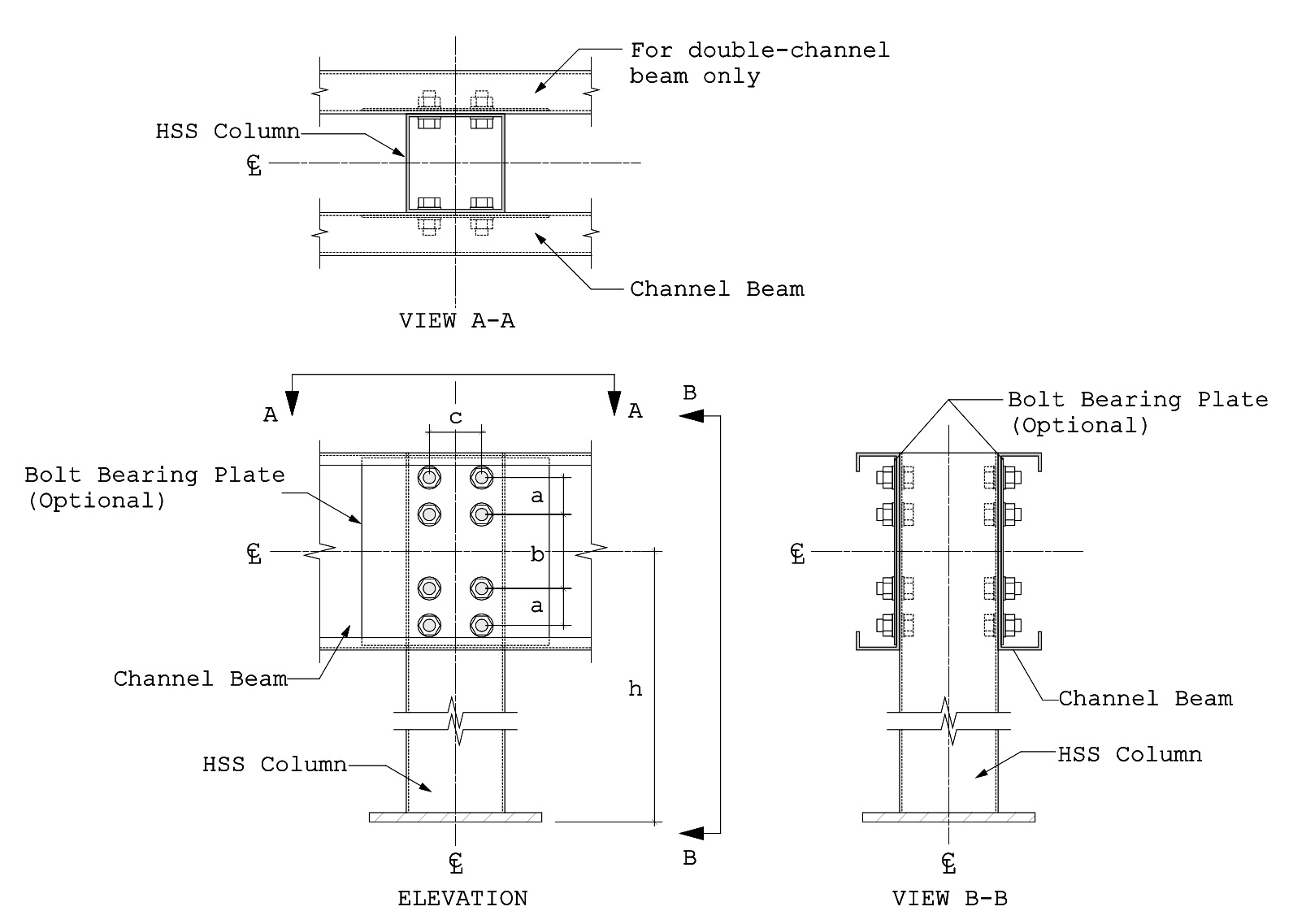
Figure 3. Cold-formed steel special bolted moment frame.
(d) Cold-formed steel special bolted moment frames SFRS: This system is formed by cold-formed channel beams and HSS columns with bolted moment connections, as detailed in Figure 3. Seismic energy is dissipated through sliding and bearing deformations in the bolted connections between the beams and columns. The beams and columns, therefore, need to be designed to resist the expected moment (Me) and shear (Ve) at the bolted connections defined as:
Ve = (VS + VB) (AISI S400 Eqn. E4.3.3-1)
Me = h(VS + RtVB) (AISI S400-C Eqn. C-E4.3.3-1)
VS = column shear corresponding to the slip strength of the bolt group;
VB = connection bearing component of column shear corresponding to the displacement
∆ (design story drift)
h = height from column base to the centerline of the beam
Rt = ratio of expected tensile strength to specified minimum tensile strength
Detailed guidance on how to determine the expected strength is provided in the standard.
Currently, this SFRS has a number of limitations that are further detailed in AISI S400, Section E4. For instance, it is limited to single story structures no higher than 35 feet.
(e) Cold-formed light frame shear walls with gypsum board or fiberboard panel sheathing SFRS: This SFRS has a similar designated energy dissipating mechanism as described in Section (a). The system is designed as Type I shear walls with h/w ≤ 2, and wall-length ≥ 24 inches. The nominal shear strength and detailed requirements are provided in Section E6 of the standard.
The expected strength of this SFRS equals 1.5 times the nominal strength.
Chapter F
This chapter outlines requirements for Diaphragms. Acting to collect and distribute seismic forces to the SFRS, diaphragms must be designed to resist the forces specified by the applicable building code. The diaphragm stiffness needs to be taken into consideration in determining the required strengths of both the SFRS and the diaphragm itself since the stiffness directly affects the force distribution. This standard currently provides the design provisions for cold-formed steel-framed diaphragms sheathed with wood structural panels. Future editions may be extended to include other common diaphragm systems.
Chapter G
This chapter discusses Quality Control and Quality Assurance. The cold-formed steel shear walls and strap-braced walls follow the QC and QA provisions provided in AISI S240, Chapter D, which includes requirements for lateral force resisting systems. For CFS special bolted moment frames, the QC and QA requirements are provided in AISI S400, Section G4.
Chapter H
This chapter, Use of Substitute Components and Connections in Seismic Force-Resisting Systems, permits the substitution of components or connections in any of the SFRS specified in Chapter E as long as they follow the applicable building code requirements and are approved by the authority having jurisdiction. This is intended to dovetail with ASCE 7-16 Chapter 12, which provides general guidance on this topic.
In Conclusion
AISI S400 and all AISI published design standards can be downloaded from the website www.aisistandards.org. A design guide for the seismic design of cold-formed steel framing will be published in 2018.▪
Design Example
Determine the nominal shear strength of the strap braced wall, as illustrated in Figure 4a, and the expected strength of the system. The shear wall width, w = 6 ft; height = 10 ft; strap size = 5 in × 54 mil (t = 0.0566 in), Fy = 50 ksi, Fu = 65 ksi; from AISI S400, Table A3.2-1, the material expected strength factors, Ry = 1.1 and Rt = 1.1
The strap nominal strength:
Ag = (5)(0.0566) = 0.283 in2
Tn = AgFy = (0.283)(50) = 14.15 kips (AISI S400 Eqn. E3.3.1-2)
Nominal shear strength of the wall:
Vn = Tnw/√w2 + h2 = 14.15 × 6/√62 + 102 = 7.28 kips (AISIS400 Eqn. E3.3.1-1)
Safety and resistance factors: Ωv = 1.67 φv = 0.90
The available strengths of the wall:
For ASD: Va = Vn/Ωv = 7.28/1.67 = 4.36 kips
For LRFD: Va = φv Vn = (0.9)(7.28) = 6.55 kips
Unless a welded connection is used, the connection needs to satisfy the following condition:
(RtFu)/(RyFy)=1.3 > 1.2 OK (AISI S400 Eqn. E3.4.1-1)
RtAnFu>RyAgFy (AISI S400 Eqn. E3.4.1-2)
An = (5-3(0.19))(0.0566) = 0.251 in2 (Based on (3) fasteners with 0.19-inch diameter across the strap width (Figure 4b). Therefore, (1.1)(0.251)(65) = 17.95 kips > (1.1)( 0.283)(50) = 15.6 kip OK
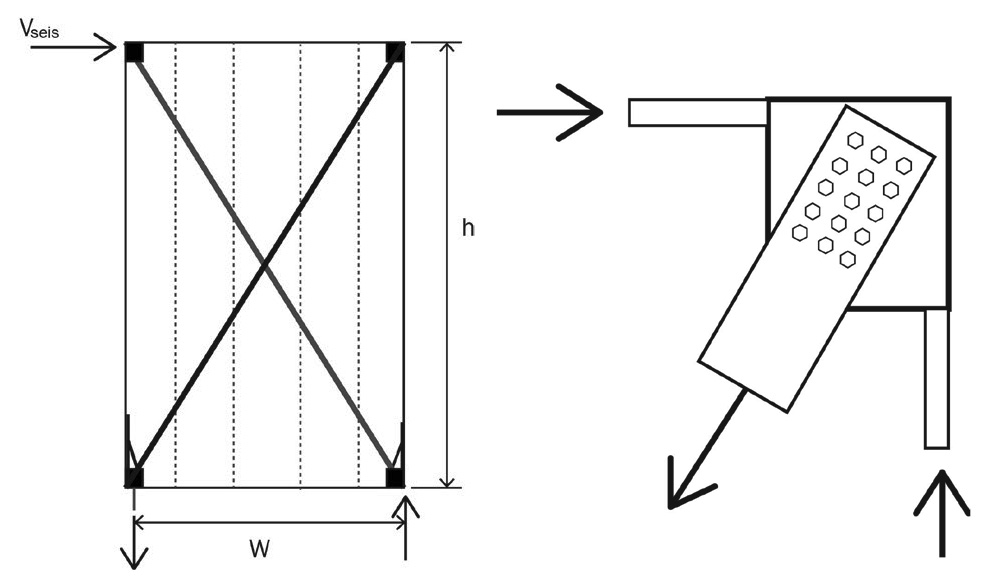
Figure 4. Braced shear wall design example. a) Strap Braced shear wall; b) Connection.
Strap expected strength:
RyFyAg = (1.1)(50)(0.283) = 15.6 kips
Collectors, strap connections, chord studs, other vertical boundary elements, hold-downs and anchorage connected to it and all other components and connections of the strap braced wall should be designed to resist this force.
References
NBCC, National Building Code of Canada, 2010 Edition
American Iron and Steel Institute, AISI S213-07w/S1-09(2012), North American Standard for Cold-Formed Steel Framing–Lateral Design, 2007 Edition with 2009 Supplement (Reaffirmed 2012).
American Iron and Steel Institute, AISI S110-07 w/S1-09(2012), Standard for Seismic Design of Cold-Formed Steel Structural Systems – Special Bolted Moment Frames, 2007 Edition. with 2009 Supplement (Reaffirmed 2012)
American Iron and Steel Institute, AISI S100-12, North American Specification for the Design of Cold-Formed Steel Structural Members
Cold-Formed Steel Framing Institute, Introduction to AISI S400, North American Standard for Seismic Design of Cold-Formed Steel Structural Systems.