
Charlotte Douglas International Airport
A primary feature of Destination CLT the Charlotte Douglas International Airport (CLT) in Charlotte, NC, the expansion of the airport’s Concourse A is now under construction. The overall goal of the Concourse A Explansion – Phase I (Phase I Expansion) is to enhance the arrival and departure experience of regional and connecting travelers while providing new gates to accommodate existing and future growth at CLT, ranked among the nation’s 10 busiest airports.
This multiphase project will ultimately provide up to 27 new gates, with 9 new gates completed under Phase 1 now under construction. The new concourse is connected to the main terminal with a 750-foot corridor which will provide areas for services and be energized with art both inside and outside.
The Phase I Expansion is sited along the main entry drive to the airport terminal. The new concourse and connector’s location and signature architectural expression will go far in providing a new “gateway” to the airport.
The Team of Perkins+Will and CDesign, with Stewart Engineering providing structural design services, designed a simple yet dynamic structure composed of an arched roof which is asymmetrical to the north to allow for maximum daylight into the concourse. The structure for the large overhanging roof is enclosed between metal roof panels and a slightly reflective interior ceiling. The overall result is a wing-like roof that hovers over the concourse spaces below.
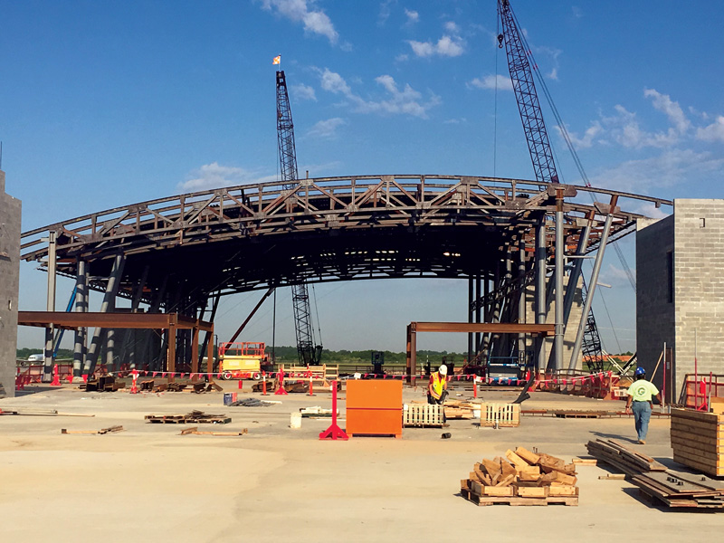
Erection of arched steel trusses spanning the width of concourse over the elevated concrete slab.
Exposed V-shaped steel columns support the roof, which reflects the asymmetrical geometry of the concourse, and change from the south to the north to accentuate the sense of motion implied within the structure. By use of both standardized and custom-designed steel castings, the design team was able to achieve functional, architecturally exposed structural steel (AESS) connections that seamlessly tie the columns together and elevate the exposed structure into something spectacular.
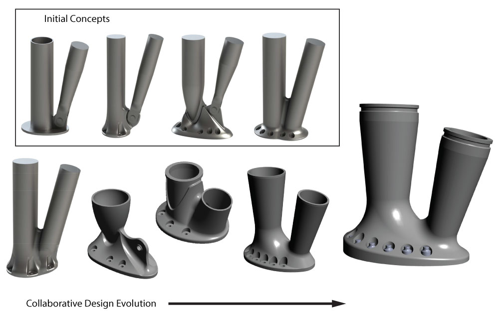
Conceptual design development of custom cast steel bases.
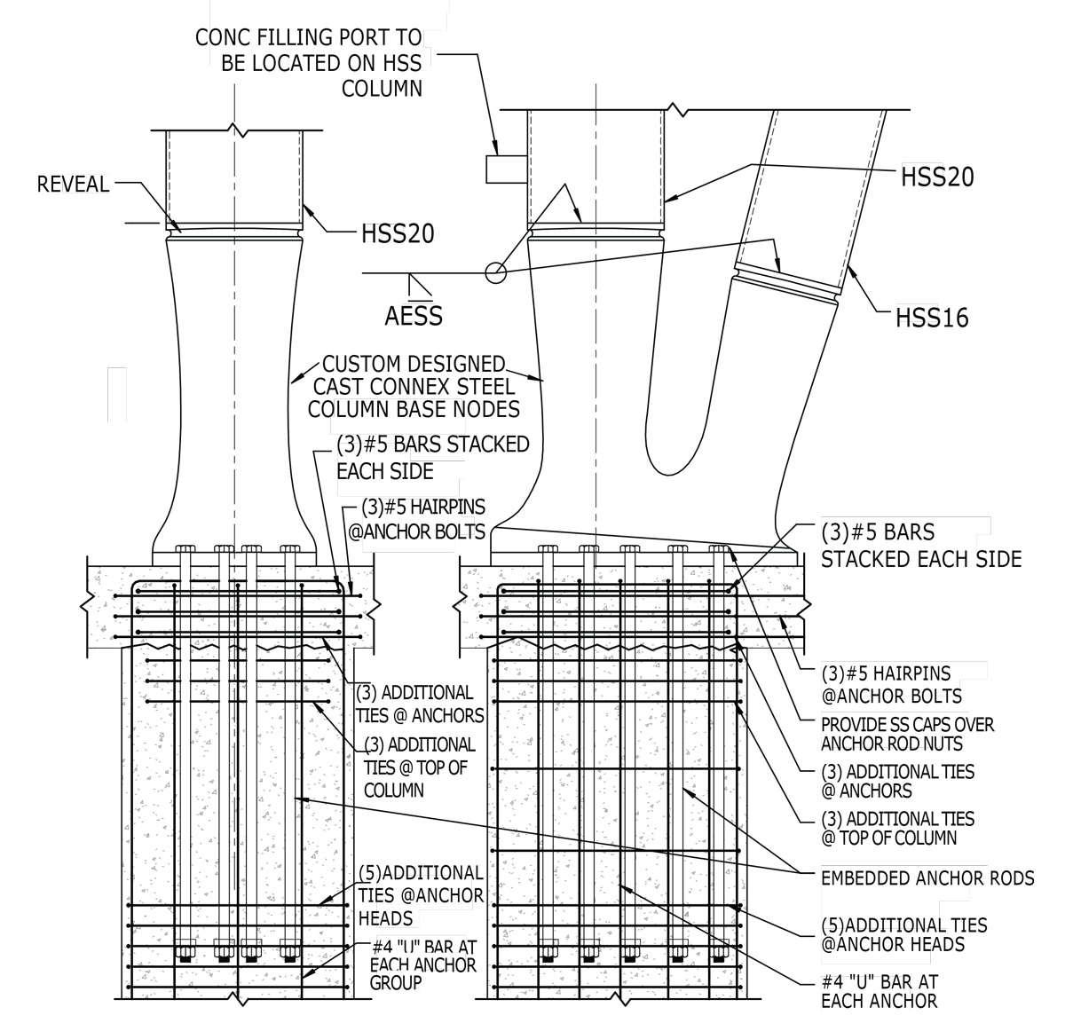
Custom designed cast steel column base node details as shown in the structural set.
Challenges
The expansion posed several structural challenges in the concourse and connector areas. These issues included a long span roof with a high arched roof structure, a low clearance between the tarmac and the first elevated floor, expansive glass walls throughout the entire concourse and a very long connector area, which includes people movers, and service features below for storage, mechanical, tugs, and luggage circulation.
The roof structure used arched steel trusses, which span the 105-foot concourse width. The trusses were relatively shallow, at a depth of 8 feet to stay within the arching ceiling space, and were spaced at 15 feet on-center to support the long span steel decking. The spacing resulted in every other truss framing into the columns with the remaining trusses supported on transfer beams. The trusses consist of arched wide flange top and bottom chords with wide flange web members. The truss members are connected with bolted plate connections. The trusses cantilever 17 feet past the supporting columns as they taper to form a “wing” point on the edge of the roof. The roof was cantilevered in all four directions resulting in a particular challenge at the corners due to the cantilevered roof framing extending in both directions.
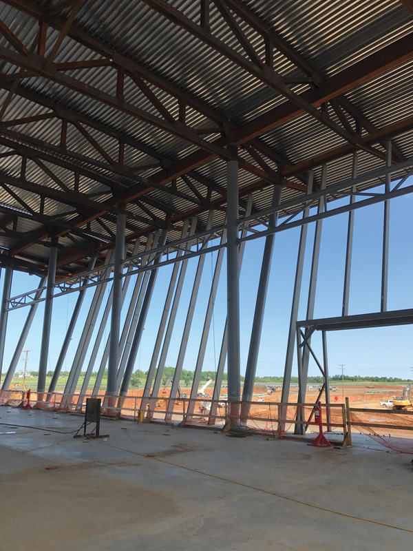
Completed cantilevered truss ends, arched decking, and wind girt system at the sloping exterior wall with the “V” columns.
The low clearance below the elevated first floor required a shallow structure to maximize the open space below for operations. The design team determined that the most economical system that met clearance and vibration requirements was a two-way concrete 12-inch slab system supported on concrete columns. The team designed the space below to allow a conventional 30-foot by 30-foot grid. The concrete slab system also facilitated a seamless support for the recessed walkways which extended the full length of the connector. The concrete structure also provided the needed rigidity to resist seismic and wind loads. Due to the open floor plan and building function, vibration was an important design constraint best addressed by the concrete structure.
The V-shaped hollow structural steel columns were located on either side of the concourse. The columns supported the roof trusses and the wind girt structure of the glass walls. The exposed wind girt structure consisted of hollow structural steel members spanning vertically with the window mullions. The angle of the “V” columns supported the sloped glass wall, which leaned outward over the full height of the structure.
The lateral system of the building had high demands due to the 55-foot tall clear-story roof, the tall walls, and the 90 MPH wind speed with a wind exposure C at the airport site. The lateral system also needed to support the required blast loading on the structure. The steel portion of the lateral system utilized the steel trusses on round hollow structural steel columns as moment frames. Each of the round columns consisted of two columns connected at the base and extending apart forming the “V.” The lateral system along the length of the concourse consisted of moment frames using steel beams, which spanned between the HSS columns along with the addition of steel lateral trusses within the wind girt systems along the perimeter. The building contained a steel framed mezzanine for a portion of the concourse, which also assisted with the lateral support of the building. The concrete lower level of the building used reinforced concrete shear walls.
The long-span, tall-truss moment frame resulted in significant vertical and horizontal loads and overturning demand at its base. The peak reaction forces at the underside of the cast node were in the range of 840 kip-ft and 260 kip-ft in the in-plane and out-of-plane directions, respectively; 460 kip peak compression; 10 kip net uplift; and 100 kip shear at the base. These loads had to be transferred to the concrete columns below, through the elevated concrete slab. It was not possible to recess the column connection below the slab due to the required connections between the concrete slab and the concrete columns below. This meant the connection had to be located above the slab level where they would be exposed. The connection also needed to accommodate the two columns framing into a single point to form the “V.”
Custom Castings
Initially, a standard steel connection was designed to transfer the loads at the column. This consisted of a series of welded vertical and horizontal plates with large anchor bolts. Due to the geometry and the significant loads, the connection became very large and was not aesthetically pleasing for an exposed condition. The exposed anchor bolts projecting above the baseplate were also undesirable and were unsafe with people walking throughout the area.
Consequently, the design team was excited to explore the benefits of the casting process. Key features of the base design included:
- Integrate dual column for structural support and bracing into a single sculptural base
- Fire-resistance rating for steel casting required concrete fill to prevent the need for intumescent paint coating on the castings
- High-performance coating on the base to transition to Intumescent paint above the casting datum line
The resulting nodes are over four feet tall and have an oviform four-foot by three-foot base with expressive counterbores to accommodate field installation and anchorage to the reinforced concrete base. At a weight of over 4,000-pounds, the castings are designed to be filled with concrete after being set, thereby negating the need for fire coatings. Finally, a purposeful reveal was designed into the casting to provide a clean transition between the high-performance coating system on the castings and the intumescent coating required on the HSS columns above.
Cast Connex provided support to Perkins+Will, CDesign, and Stewart Engineering during the design phase to facilitate the specification of structural steel castings as a delegated design item in the contract documents. Discussions with a specialized casting design-builder during a project’s design phase ensures that the resulting component is not only architecturally appropriate and structurally adequate but also that the design is economically castable and best leverages the advantages of casting manufacturing to the benefit of the project.
The collaborative design process commenced with the development of four initial concepts by the casting design-builder, followed by successive iterations of input by the design team and remodeling to address aesthetic preferences and functional needs. Augmented reality visualization – where 1-to-1 scale, 3-dimensional design models were superimposed over the user’s view of the real world – was employed to study and convey the design concepts for consideration through the process. This technology, quickly becoming mainstream, was a valuable tool for exploration and decision-making.
As noted above, the need for a 2-hour fire resistance and the desire for the base to be painted with a high-performance coating rather than intumescent also drove the design. Ultimately, fire resistance requirements drove the design away from a pin-connected inclined column to a welded connection at the base. The wall thickness and concrete fill volume of the cast node were then proportioned to achieve the 2-hour fire resistance as confirmed via 2-dimensional heat transfer analysis conducted by The Fire Consultants of Apex, NC.
Once the conceptual design of the base was finalized, structural and architectural drawings were updated to show the cast steel components diagrammatically. When so doing, it is important to provide the overall dimensions of the casting, its general configuration, and its relationship and connectivity to other structural elements.
Also, the casting design-builder provided a template performance specification for the castings. This formed the basis for a subsection of the division 05 specification on the steel castings. The specification a) delegated structural design responsibility to the casting supplier, b) clearly defined the roles and responsibilities of both the steel casting supplier and the steel fabricator, and c) outlined structural performance and aesthetic requirements (structural loading and surface finish requirements, for example) for the castings. Cast Connex did not charge any upfront consulting fee for the support provided during the design phase of the project; however, Cast Connex was the specified manufacturer of the specialty design-built elements. As procuring and incorporating the castings into the structural steel framework was left within the scope of the steel fabricator, Cast Connex provided their design and manufacturing proposal to all steel fabricators bidding on the project.
Post-Tender Casting Engineering and Construction
Cast Connex analyzed the cast steel bases by using a sophisticated finite element analysis model that included coupling constraints, contact boundary conditions, and non-linear material models to sufficiently capture the interaction between the steel columns, cast steel base, anchor rods, and reinforced concrete structure below the base. Stress and strain states from over 1,000 unique load combinations were analyzed to ensure the structural adequacy of the casting.
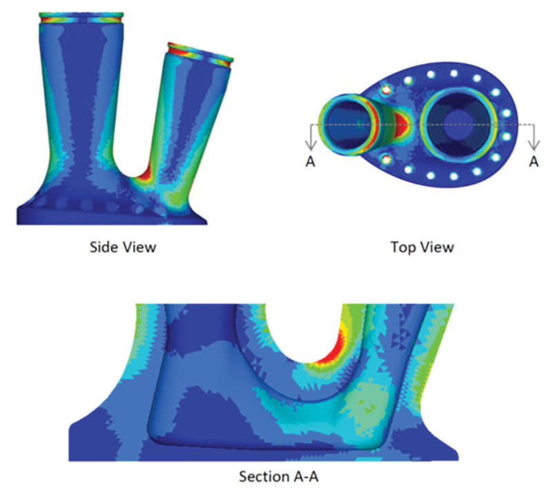
Finite element stress analysis result.
The casting design-builder created detailed casting and machining shop drawings, clearly differentiating as-cast features versus those which would be machined. They also coordinated and stipulated manufacturing tolerances, casting non-destructive examination criteria, material chemistry and heat treatment, and all other production parameters necessary to ensure the manufacture of castings that are fit for purpose.
Finally, Cast Connex provided support to CMC Structural on all aspects of fabricating with steel castings, including providing technical support related to the development and qualification of welding procedure specifications (WPS) via procedure qualification records (PQR) and testing for welds to be applied between the various cast and rolled steel products.
Conclusion
The design of the Concourse A Expansion – Phase I will provide a new “threshold” experience for CLT and will accommodate future growth and flexibility for change. The architectural expression works well with the existing architecture of the main terminal but provides a new “spin” on the way structure and architecture are realized. By concealing the roof trusses and expressing the structural columns, the team seized the opportunity to articulate the column bases where passengers will have a direct, visual connection. The proportion, finish, and required code ratings all worked to drive a solution that was achieved by leveraging the benefits of steel casting. The cast bases and frame connections serve as a functional solution and provide dramatic sculptural and artful detail intrinsically valued by the architectural team. The final product is one that is both beautiful and functional, something that will be enjoyed by travelers for years to come.▪