
Two days of expected work turned into a week; one equipment breakdown cascaded into another; a 30-minute delay became 24 hours. A documentation project that was scheduled to happen in June did not begin until September. The challenges of keeping a bridge demolition project on schedule are not unique, but the requirement for historical documentation of a 1912 reinforced concrete bridge by historians and engineers added another layer of complexity to a highway widening project. However, this documentation effort ultimately provided interesting information about the early development of reinforced concrete flat slab design.
The historians’ involvement was prompted by a routine set of circumstances. The structure in question, Bridge No. 92297 – enumerated as part of a statewide inventory of highway bridges – was being demolished in order to facilitate a joint Minnesota Department of Transportation (MnDOT) and Federal Highway Administration (FHWA) project to reconstruct and widen a section of the adjacent Interstate Highway I-35E in St. Paul. The FHWA provided federal dollars, which triggered the process known as a “Section 106 review.” Passed in 1966, the National Historic Preservation Act (NHPA) created the National Register of Historic Places and requires all federal agencies to take historic resources “into account” when funding, permitting, or licensing undertakings. Section 106 of the NHPA describes a process of planning for preservation in advance of construction.
For this project, MnDOT retained Summit Envirosolutions, Inc. as the cultural resource consultant to complete the initial portion of the Section 106 review: identifying historic or potentially historic resources by researching properties and structures in the area that would be affected by the highway expansion. Through this process, the consultants determined that Bridge No. 92297 was historically significant. In instances when a federally funded project affects a historic resource, the project agency must work with the State Historic Preservation Office (SHPO) to determine how best to mitigate the impact. Options can range from major changes, such as re-routing a proposed road, to documenting the historic structure prior to demolition, as was the case with Bridge No. 92297. The pending demolition of the bridge presented a unique opportunity to investigate the steel reinforcement concealed within the structure. The team conducting the sequenced research, documentation and demolition included Summit Envirosolutions, Preservation Design Works (PVN), a photographer, MnDOT engineers, and the contractor.
Bridge No. 92297 was a monolithic, single-span, reinforced concrete flat slab deck with vertical abutments supported on reinforced concrete strip footings, constructed in 1912 (Figure 1). It was oriented on a 35-degree skew, measured 49 feet in total length, and had a clear span of 41 feet with a 60-foot-wide deck. Without any background about its history, the bridge would have appeared rather unremarkable. However, research on the bridge revealed that it was an innovative design for its time. Its documentation shed more light on the work of the bridge’s designer, and also created a record available for future study.
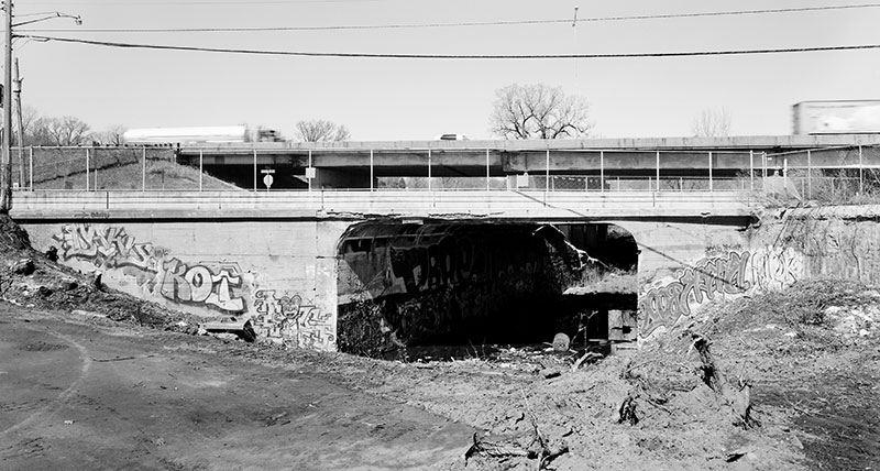
Figure 1: Bridge No. 92297 shortly before demolition. Photograph by Daniel R. Pratt, courtesy of MN Historical Society Archives.
C.A.P. Turner and the Flat Slab
Claude Allen Porter (C.A.P.) Turner, a Minneapolis-based structural engineer, was a pioneer in the development of the reinforced concrete flat slab and designed bridge No. 92297. According to several articles by Dario Gasparini, Turner was born in Lincoln, Rhode Island in 1869, and graduated from Lehigh University in 1890. He subsequently worked for various bridge companies until 1901, when he began his own consulting firm with the Minneapolis, St. Paul and Sault Ste. Marie Railroad (the “Soo Line”) as a principal client (Gasparini, 2002). As Turner progressed in his career, he expanded his practice to the design of buildings, including the first one in Minneapolis with reinforced concrete floors and columns in 1904. His major breakthrough in concrete design would be realized two years later: in 1906, Turner designed his first building with the “mushroom” system of flat slab floors, the Johnson-Bovey building in Minneapolis (now demolished).
In the next few years, implementation of Turner’s proprietary flat slab floor system grew at a furious pace. His design consisted of floors with four-way reinforcement supported directly on reinforced concrete columns, each with a distinctive flared capital. Between 1906 and 1910, Turner claimed that buildings constructed with his system were “rapidly approaching a thousand acres of floor” (Turner, 1910; 7-12). This growth can be attributed in part to his extensive publication of designs and load test results for his flooring system in nationally prominent engineering journals, which proved their reliability and cost-effectiveness. However, a series of patent lawsuits and countersuits beginning in 1911 resulted in a dramatic downturn in the use of Turner’s flat slab system. Nevertheless, he substantially contributed to the acceptance of reinforced concrete flat slab technology among practicing engineers (Gasparini, et al., 2001; 17-21).
In addition to implementing his system in buildings, Turner designed several reinforced concrete flat slab bridges, most as adaptations of his mushroom floor system. To date, all known flat slab bridges in the Twin Cities designed by Turner have been demolished. The bridge decks were often designed with four-way reinforcement similar to his floors, with longitudinal, transverse, and diagonal steel. With the exception of a tunnel originally located not far from the area studied for this project, Turner’s published examples of flat slab bridges did not bear much resemblance to Bridge No. 92297 (Gasparini, et al., 2001; 12-27). However, Turner held a number of related patents for both floor systems and bridges, one of which bears a striking resemblance to Bridge No. 92297, particularly the configuration of the abutment reinforcement (Figure 2).
Figure 2: Excerpt of C.A.P. Turner’s U.S. Patent 1,002,945: “Short-Span Flat-Slab Bridge,” filed October 1, 1909. Although the deck reinforcement of Bridge No. 92297 did not resemble the design in this patent, the profile of the deck, abutments, and footings, as well as the abutment reinforcement bears a striking resemblance. Digitized by Google Patents.
Copies of construction drawings and plans dating to the erection of the bridge, as well as correspondence between the Soo Line railroad engineers and the city of Saint Paul engineers, revealed some insights into the bridge’s design and also raised questions. Although the discovery of original drawings was fortuitous – and rare for a structure of this age – the copies were of poor quality and only partially legible (Figure 3). Of the six sheets in the set, one was stamped with “CAP Turner Consulting Engineer” in the title block, while the “Chief Engineers Office” of the railroad was stamped on the remaining sheets. The date of the sheet stamped with Turner’s firm was illegible, but several of the sheets stamped by the railroad engineers were clearly dated to 1912. The correspondence between engineers indicates that plans were originally drawn for the bridge in 1908, and then were revised in 1912 because the earlier plans did not meet the standards of the 1907 city ordinance. Summit Envirosolutions postulated that the drawing sheet stamped by Turner was part of the original 1908 set, and the remaining sheets were a revision of Turner’s design made by the railroad’s engineers.
Figure 3: Original construction drawing of plan and elevation of Bridge No. 92297.
Interpretation of the original drawings was also hampered by their poor legibility and a lack of corresponding notes or engineering calculations. This was compounded by the fact that changes had obviously been made to the bridge after its construction, such as the replacement of the railing and the installation of a new topping slab, which complicated efforts to differentiate original and more recently added features. Despite these difficulties, comparison with observed conditions, the original drawings, and Turner’s patent for a similar bridge design, led to the conclusion that the structural design of the bridge can be substantially attributed to C.A.P Turner.
The complications that the team experienced in reading the Bridge No. 92297 drawings are actually typical obstacles to understanding historic engineering structures. Any engineer asked to retrofit an older building can relate to the frustration of not being able to locate the original engineering design drawings; while architectural drawings are often kept as much for their visual appeal as their content, engineering drawings are often inadvertently lost, or even intentionally destroyed for insurance and liability reasons. Likewise, details of the construction methods and sequence may never have been recorded, but rather negotiated in the field by a contractor or builder. Finally, the structure itself is often concealed, limiting the ability to measure and record the structural elements. While deconstruction is not often considered an ideal method of research, the removal of this 1912 bridge presented an opportunity to gain additional knowledge of early flat slab bridge design.
Deconstruction and Documentation
Bridge No. 92297 was documented to Minnesota Historic Property Record (MHPR) standards. MHPR is a modified version of the national standard Historic American Engineering Record (HAER) program. The HAER program documents nationally significant historic mechanical and engineering structures and sites; the extensive collection is digitized and available to the public on the Library of Congress website (www.loc.gov/pictures/collection/hh/). Both programs maintain documentation of historic resources, and have a target archival life of 500 years. The MHPR materials for Bridge No. 92297 included a report with a written description, large format photographs, and measured drawings of selected areas of the bridge highlighting its design and construction.
Deconstructing and documenting a historic bridge requires time, care and coordination that is not required with standard demolition and removal (Figure 4). Determining the configuration of reinforcement for comparison to the original construction drawings required investigative openings in areas that would expose representative samples of reinforcement in the bridge deck, abutments and footings. Maintaining stability of the bridge to allow for safe access after its partial demolition, as well as to expose sections of the abutments and footings, required an extensive amount of earthwork.
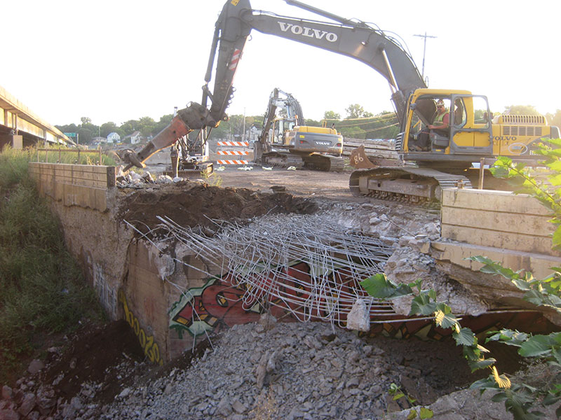
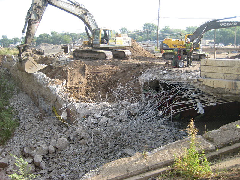
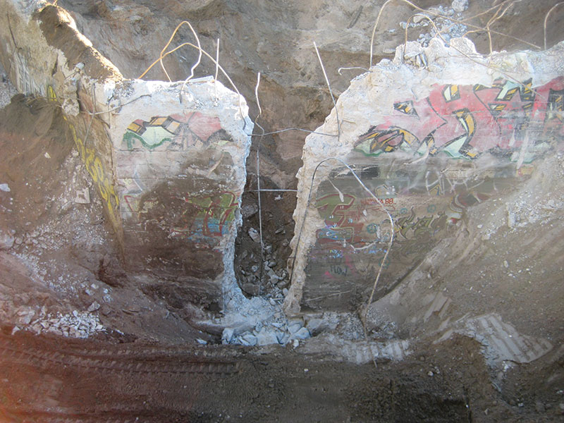
Figure 4: Careful demolition of the bridge revealed the reinforcement, facilitating its documentation in selected areas.
A two-stage demolition process accommodated the documentation process. Backhoes equipped with hydraulic jackhammers removed concrete in selected areas of the bridge to expose reinforcement. Fill placed below the bridge stabilized the abutment walls during the exposure and removal of the deck. Two full-depth openings in the bridge deck – one near the middle, and another along the edge and the adjoining transition into the top of the abutment – facilitated its documentation before complete demolition. Next came excavating soil on both sides of the abutment to the top of the footing, then removing concrete from the selected area to expose the underlying reinforcement. The investigation team took measurements and photographs all along the way.
This investigative process was hampered by poor accessibility of the machinery, especially after demolition of the bridge began to compromise its ability to support heavy loads. There were several equipment breakdowns, and the existing concrete was stronger than expected in some locations. These issues created unforeseen delays that impacted the demolition schedule. Despite the slower than expected progress of the work, careful operation resulted in exposure of the majority of the reinforcement with minimal changes to its as-built configuration. The destructive nature of the work resulted in some deformation or breakage of the reinforcement being recorded. In these cases, carefully exposing adjacent sections made it possible to document the typical configuration of reinforcement as originally placed.
The plan and profile of reinforcement was generally congruent with the original construction drawings from 1912, with the exception of minor details and extra reinforcement along the fillet corner in the deck-to-abutment transition. The skewed geometry of Bridge No. 92297 was not well-suited to Turner’s patented short-span bridge design, but the two layers of slab reinforcement in the bridge were similar to the configuration of diagonal reinforcement in Turner’s patent. One layer of slab reinforcement was placed parallel to the span of the bridge, and the other layer was placed perpendicular to the abutment walls. Some transverse reinforcement was present, which correlated with the patent, but it was so widely spaced – over five feet on center – that its intended purpose was likely just to support the draped geometry of the two primary layers of slab reinforcement. The profile of the slab and abutment reinforcement correlated closely with the design illustrated in Turner’s patent. Because of the geometry of the bridge span, the flat slab of Bridge No. 92297 more closely resembled a one-way structural system, rather than the four-way systems found in Turner’s published designs.
Considering its age, Bridge No. 92297 was in remarkably good structural condition and continued to perform as intended by carrying heavy vehicular traffic even into the start of demolition. Despite the somewhat deteriorated condition of the bridge, including concrete spalling and substantial graffiti, its continued use had demonstrated that the early design was not only adequate for the streetcar loads at the time of construction, but also remained suited for the loading demands imposed by modern traffic.
Conclusion
Researching the history of engineering has unique and persistent challenges: structural details are concealed, drawings are often not available, and the field is relatively new compared to the more established scholarship of architectural history. However, programs such as the MHPR and HAER provide a framework for expanding this field of study. When demolition of a resource is unavoidable, documentation can partially mitigate its loss by recording and allowing for the future study of its features. Understanding the history of a profession can provide a valuable perspective on how its common practices and philosophy have evolved.
Likewise, engineers seeking to preserve or rehabilitate existing structures can benefit from studying previously documented and demolished examples for the insights that they provide into design and construction. Bridge No. 92297 offered a unique opportunity to document the details of the steel reinforcement in a historic reinforced concrete structure, a task that is – for obvious reasons – generally infeasible for such structures that are to remain intact.▪
References
Dario A. Gasparini, Contributions of C.A.P. Turner to Development of Reinforced Concrete Flat labs 1905-1909, J. Structural Engineering 128 (October 2002).
C.A.P. Turner, The Mushroom System as Applied to Bridges, Cement Age X (January 1910).
Dario A. Gasparini and William Vermes, C.A.P. Turner and Reinforced Concrete Flat Slab Bridges, Proceedings of the 7th Historic Bridges Conference, September 19-22, 2001, Cleveland, Ohio.