
A straight-line wind event took place in Rockwall, Texas, March 29, 2017, producing significant structural damage resulting in four red- and five yellow-tagged homes. The National Weather Service in Fort Worth estimated the storm’s wind speed to be 100 to 110 mph. Before demolition of the most impacted home (Figure 1), APA – The Engineered Wood Association (APA) field staff followed through with an opportunity to survey the damage.
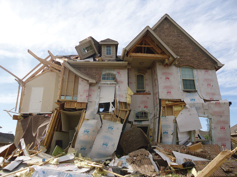
Figure 1. The March 2017 straight-line wind event took place in Rockwall, Texas, produced significant structural damage.
The same fundamental design principle used for resisting tornadoes and hurricanes is also used to resist straight-line winds: create a continuous load path from the point of origin to the foundation. As demonstrated by the March 2017 storm, straight-line winds can be just as destructive as tornados and can produce estimated wind speeds within the bounds of the International Residential Code (IRC).
Continuity in wood-frame construction can be accomplished in many ways, most commonly with continuous wood structural panel (WSP) sheathing of the building envelope. Using a WSP, such as oriented strand board (OSB) or plywood, creates structural redundancy, enhanced puncture resistance from flying debris, and protection from wind-driven rain. In storm events, water damage to a building’s contents can be more costly than the structural repair itself.
In APA’s assessment of the damage, actual construction detail deviated from recommended practices. The following overview highlights some of the more important structural issues.
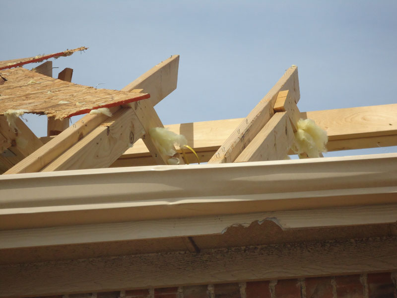
Figure 2. This roof had many staples oriented perpendicular to the rafter, and several staples
had only one leg in the rafter.
WSP roof sheathing was stapled to the roof rafters and, while code allows for staples, proper installation is critical. The roof in Figure 2 had many staples oriented perpendicular to the rafter, and several staples had only one leg in the rafter, which combined to reduce the capacity of the connection by at least 50 percent. The staple crown should be parallel to the rafter to assure both legs are embedded into the supporting member. The staples also appeared to be fastened in an inconsistent pattern.
For these wind speeds, APA recommends using 8d ring shank or screw shank nails (0.131-inch x 2½-inch) fastened at 4 inches on-center along the WSP perimeter and 6 inches on-center in the WSP interior. This nailing pattern is closer than the minimum 6- and 12-inch-on-center spacing pattern to provide additional uplift resistance in high-wind events.
The roof diaphragm transfers the lateral load to the shear walls below. In residential construction, this is often the exterior walls of the home in the form of wall bracing or engineered shear walls. Wall bracing is a prescriptive method in the IRC, with the same objective as shear walls. A wood-framed shear wall transfers the shear force via the capacity of the sheathing and the attachment of that material to the supporting wood studs, resists sliding of the base with anchor bolts, and prevents overturning of the wall, conventionally by using hold downs.
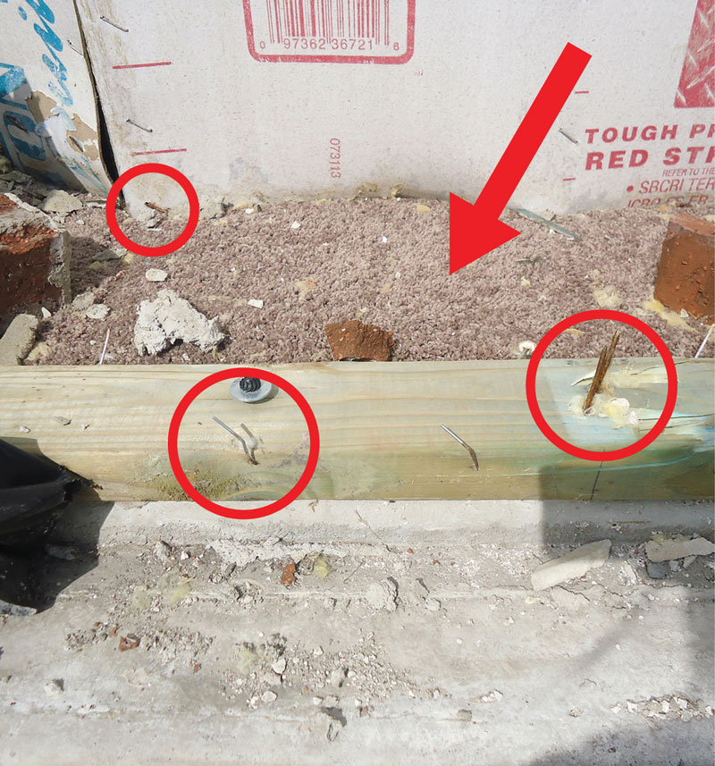
Figure 3. The flexible sheathing tore away from the bottom plate where staples were only partially embedded, allowing the balance of the wall to move inside (note that the arrow is pointing at the carpet).
In the observed homes, there was a lack of load path continuity. The wall sheathing panels were not attached to the top plates, had no lateral load transfer at the floor line, and the attachment to the walls studs failed (Figure 3).
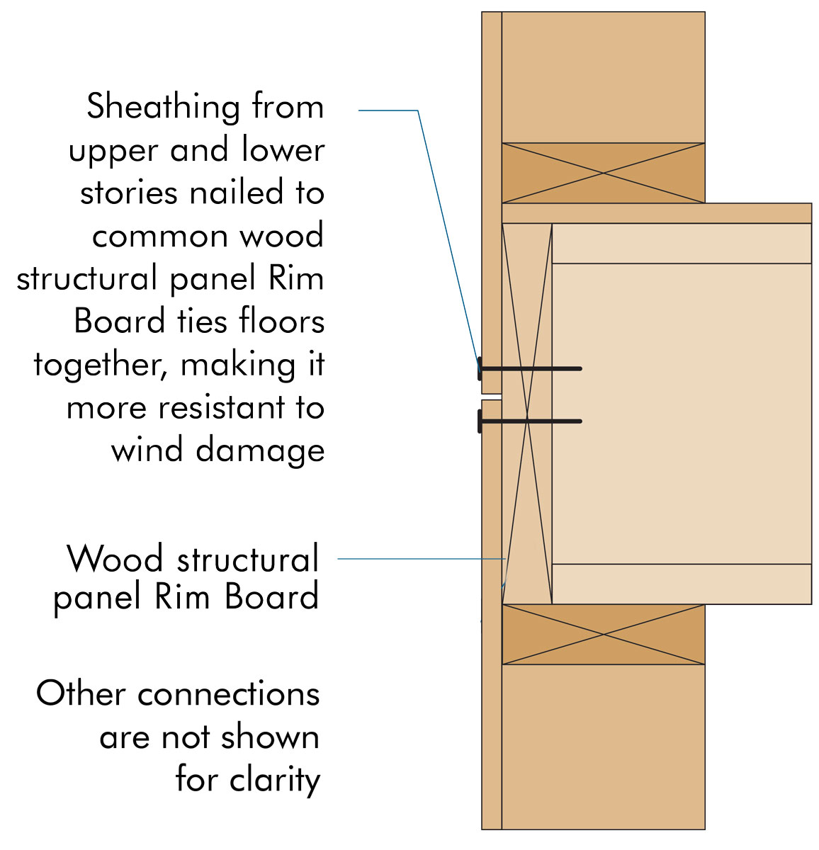
Figure 4. Creating load path continuity from floor to floor using WSP wall sheathing lapped over the fastened.
The detail in Figure 4 shows wall sheathing lapped over the Rim Board® and fastened as one way to create load path continuity from floor to floor. Another way is to use metal plates, such as Simpson Strong-Tie® LTP4s, although neither was done here. Instead, flexible sheathing of various grades (load capacities: structural grade and non-structural grade infill) was fastened using staples. The non-structural grade sheathing installed over the rim board made it impossible to determine the amount of load transfer available. The wall sheathing was punctured and missing as shown in Figure 1, which created an opportunity for moisture damage on the interior contents and possible internal pressurization of the home leading to more structural damage.
The flexible sheathing tore away from the bottom plate (Figure 3) where staples were only partially embedded, allowing the balance of the wall to move inside (note that the arrow is pointing at the carpet). The circles on the left of the photo highlight the staples in the wall sheathing and bottom plate. The circle to the right shows the nails that had held the stud to the plate. The nails were rusted and the wall sheathing had water stains, indicating that moisture may have played a role in weakening this assembly.
The houses observed were intermittently braced with structurally graded flexible laminated-fiber sheathing, infilled with non-structural flexible laminated-fiber sheathing panels (Figure 1). Homes fully sheathed with WSP enrich the structural performance of a building. APA Report T2007-73, Full-Scale 3D Wall Bracing Tests, found continuous wood sheathing resists about 80 percent more load than intermittent WSP wall bracing.
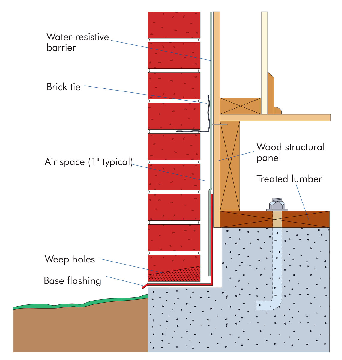
Figure 5. Code-required water-resistive barrier, flashing, and an air gap to separate the brick veneer from the wood wall.
Another observation consistent with previous tornado damage assessments was brick façade failure. Many homes in North Texas have a brick or stone veneer around the exterior of the home. In Figure 6, the brick ties failed; some stayed in the brick veneer and others attached to the wood studs. Installation of continuous WSP sheathing would allow the brick ties to be attached directly to the panels, ensuring a secure hold and reduced failures. From an engineering perspective, it is important to educate clients so that they understand that brick veneer is merely serving an aesthetic purpose – it is the sheathing attached to the studs that provides the lateral resistance and high-wind protection to the building.
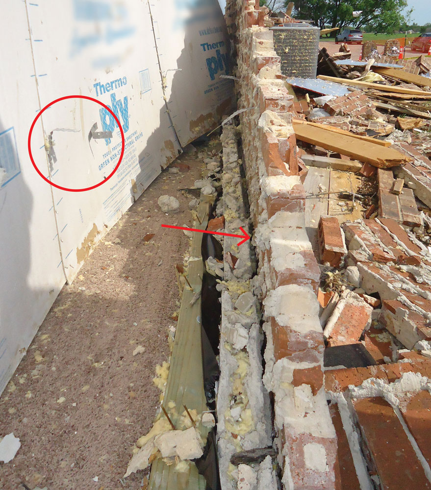
Figure 6. Damage consistent with previous tornado assessments – circle shows brick façade failure, arrow points to mortar buildup between bottom plate and brick veneer.
Structures with incomplete drainage paths are susceptible to water damage and other structural problems. Architects and engineers often detail the drainage system of a structure to avoid these moisture-related issues. As noted before, rusted fasteners and water staining on the sheathing were indications of moisture exposure. Compare Figure 5 and 6, APA’s recommended drainage assembly with one of the walls observed. In Figure 5, the wall sheathing is protected by a code- required water-resistive barrier, flashing, and an air gap to separate the brick veneer from the wood wall. The arrow in Figure 6 points to mortar buildup which occurred between the bottom plate and the brick veneer. This could trap water behind the wall which could infiltrate the wood wall assembly.
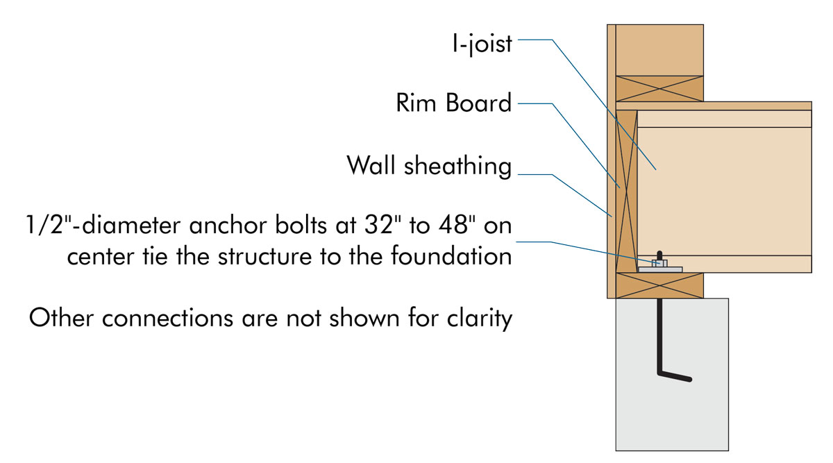
Figure 7. Use larger washers to tie the structure to the foundation better.
The last takeaway from the straight-line wind event relates to the attachment of the anchor bolts. For high wind areas, APA recommends using an oversized, 0.229-inch x 3-inch x 3-inch slotted square plate washer, four feet on-center or less, to reinforce this connection (Figure 7). Wood is weaker when loaded perpendicular to grain and an uplift force on the bottom plate creates such a load in cross-grain bending. The larger washers are a better way to tie the structure to the foundation.
Load path continuity is necessary for all structures, from homes to skyscrapers, built from wood, steel, or concrete to resist earthquakes or winds. Attention to detail and tying the elements together is particularly important for the lateral load path, as contractors may not be as familiar with the intention of the detailing. In wood framing, there are often multiple ways to create a continuous load path. Consider what will be most straightforward to build and even add redundancy when available. For more information on this straight-line wind event, APA recommendations, and related details available for free download, see www.apawood.org/wind-weather-seismic.▪
References
APA Texas Straight-Line Wind Damage Assessment Report (Form SP-1182)
APA. Building for High Wind Resistance in Light-Frame Wood Construction (Form M310)
APA. Build a Better Home: Moisture-Resistant Wall Construction (Form A530)
APA. Product Advisory: Laboratory Tests Evaluate Design Values of Thermo-Ply Red (Form SP-1172)
APA CAD www.apacad.org