
Part 3
Many structural engineers have not traditionally been involved in the analysis or design of building fire safety. When they have been, their focus has generally been on structural fire protection and, with some exceptions, their scope has been limited to ensuring compliance with prescriptive building code requirements for the fire resistance ratings of different building elements. However, structural fire protection is just one aspect of a comprehensive framework for building fire safety. As demonstrated by the Grenfell Tower fire in London, structural fire protection alone does not ensure the fire safety of a building or its occupants. While structural engineers may not practice in the field of fire protection engineering, it is useful for all engineers involved in building design to have at least a basic understanding of building fire safety issues.
Parts 1 and 2 of this series (STRUCTURE, January and February 2018), detailed an overview of fire protection for structural engineers focused on fire safety objectives and the building systems and features used to ensure the objectives are met. Part 3 provides an overview of the emerging practice of structural fire engineering, which requires close collaboration between fire protection engineers and structural engineers. Details on the design process and emerging trends and research are highlighted.
The Role of the Structural Engineer
Based on the discussion in the previous articles, it should be apparent that the traditional role of the structural engineer in building fire safety has been limited. However, that has been changing over the past two decades or so, with the emergence of structural fire engineering as a distinct design discipline.
The design of a structure’s load resisting members account for both gravity (i.e., dead, live, snow, and rain) and lateral (seismic and wind) loads, and the resulting forces (moment, shear, and axial). In some cases, such as wind loads, complex analyses are involved, from computer modeling to small-scale wind tunnel tests, to correctly design the structural framing and fine tune the architecture to reduce the wind pressure on the building. An example of this would be the architectural and façade design of the Burj Khalifa to minimize vortex shedding.
Everything about the design, from the curvature of the façade, lateral bracing locations, and the connections, are optimized to reduce the loads applied to the building and minimize the mass of the building to reduce the overall cost. However, the applied load due to thermal action has traditionally been excluded from structural engineering design and relegated to the fire protection engineer.
ASCE 7 details eight basic combinations of the loads listed above. A structural engineer must first determine which is the most onerous case and, second, design the structural members based on that load combination. The various load combinations are based on the statistics and probability that loads never occur at their full value at the same time. However, fire and the impact of thermal loads are detailed in ASCE 7 as being “extraordinary” or “low-probability” events – the same type of classification of loads as explosions and vehicular impacts. The requirement by ASCE 7 is that the engineer is only required to check the load combination “where required by the owner or applicable code.” However, according to the National Fire Protection Association, 2.93 million structure fires occurred in the U.S. from 2010 to 2015 (NFPA, 2017). Whereas, based on the National Oceanic and Atmospheric Administration data, approximately 2,000 structures have been damaged or destroyed by earthquakes over the same six-year period (NOAA, 2017). While the design for the impact of earthquakes should not be removed or replaced from structural design, especially in areas such as the West Coast of the U.S., structural design against the impact of thermal loads should not be relegated to a low-probability event when the statistics indicate otherwise. Fire is much more than an “extraordinary” event.
Structural Response to Thermal Loads
Historically, fire protection of structures has been based on the principle of limiting temperatures and the associated strength reduction. For steel construction, as an example, the limiting temperature in ASTM E119 is 538°C. This temperature is based on the yield strength reduction of steel due to increases in temperature. At 538°C, steel loses approximately 50% of its yield strength. Fire protection measures, such as gypsum board or spray-applied fireproofing, are installed to a thickness that prevents the temperature of the steel from reaching the limiting temperature during exposure to an ASTM E119 standard time-temperature curve. The underlying principle is that, if the temperature of the steel is kept below 538°C, the structural collapse is prevented since the strength reduction factor is limited to approximately 50%.
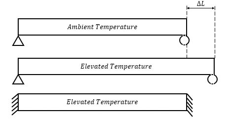
Figure 1. Thermal expansion in unrestrained vs. restrained support conditions.
However, highlighted by the Cardington Fire Tests (1995-6) and the collapse of World Trade Center 1, 2, and 7, the thermal actions of expansion and bowing occur at relatively low (150°C) temperatures and have significant effects on the structure. When typical construction materials (steel, concrete, and timber) increase in temperature, the materials expand linearly proportional to temperature (Figure 1). If the support conditions of the member – whether due to the cooler surrounding structural members or the connection type – create restraint, the member is prevented from expanding. This restricted expansion leads to high stresses within the beam and can result in local buckling at the connections during either the heating or cooling phase of a fire.
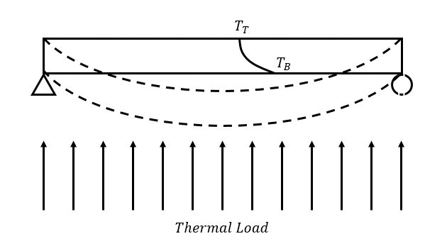
Figure 2. Thermal bowing due to differential thermal expansion from thermal gradients within a member. Unheated Member (solid lines). Thermal Bowing Member (dashed lines).
Concurrently, if the combination of the structural member’s thermal properties (insulative vs. conductive) and the applied thermal loads (large vs. small magnitudes) create thermal gradients within a member, the differential thermal expansion within the member itself can cause thermal bowing regardless of restraint conditions (Figure 2). As shown, the temperature of the bottom surface (TB) of the member is greater than the top surface (TT). As such, the bottom surface will want to expand more, relative to the top surface. Since both surfaces are part of the same member, curvature (thermal bowing) is created to account for the expansion difference. Figure 2 shows the bottom as the heated surface and that the bowing is downwards towards the fire. The reverse is true as well. If the top surface is heated more than the bottom surface, the thermal bowing would be upwards.
Holistically accounting for the structure does have benefits. When heated, a steel beam that is laterally braced by a concrete slab or a two-way spanning concrete slab can utilize tensile membrane action (catenary) and support loads at temperatures much greater than the traditional limiting temperatures. Concurrently, the surrounding structure provides a large amount of redundancy and redistribution of loads as members increase in temperature, expand, deflect, and, in some cases, fail.
While still designating fires as extraordinary events, the 2016 revision of Minimum Design Loads and Associated Criteria for Buildings and Other Structures (ASCE 7) seeks to address the impact of thermal loads on structures through Appendix E, which is a new addition to ASCE 7. The load factor combination that ASCE 7 uses adds the effects of the extraordinary event (Ak) to dead (D), live (L), and snow loads (S) with a probability factor of 1.0 (Equation 1).
(0.9 or 1.2)D + Ak + 0.5L + 0.2S Equation 1
The reasoning behind the value of 1.0 for the extraordinary event load factor is due to limited data on the frequency of the events as well as the inclusion of conservativism in the design. However, this still relies on “the owner or applicable code” (ASCE 7-16 Section 2.5.1) to require that strength and stability checks are completed and to ensure that the structure is designed against disproportionate collapse. While the structural design process for thermal loads is straightforward, the structural mechanics (described above) that are manifest when thermal loads are applied are critical in a complete understanding of the performance of a structure in fire conditions and a correct assessment of the safety of the structure. As our knowledge of structural mechanics increases with respect to thermal loads, the safety benefits by designing for thermal, mechanical action (Ak) as a substitute for temperature-limiting design criteria become more apparent.
Typical approaches to fire resistance, such as those specified in the International Building Code, place a higher fire resistance rating and thus importance on the primary structural frame (columns, bracing members, and structural members directly connected to the columns) than secondary structural members (not directly connected to the columns). Placing a higher priority on primary structural members protects against the disproportionate collapse of the structure. For designing structural members based on thermal loads, such as recommended in ASCE 7-16 Appendix E, structural members are designed based on design fires representative of the fuel load, compartment and building geometry, and ventilation conditions within the structure. Design fires are identified within the structure and the resulting thermal loads are applied to the vulnerable members. The resulting thermal, mechanical action loads (Ak) are then applied. Where necessary, protection schemes are applied to limit the influence of the thermal loads on the structure. Importance of structural members is given to areas of refuge and egress paths and any project-specifics areas that are deemed important by the owner or AHJ. Each of these steps are described in detail in the next section.
Methodology
The first step for designing structural members for thermal loads is to identify the type and amount of fuel within the compartment of the building. The type of fuel drives how quickly the fire reaches maximum heat release rate. Compartment size and ventilation conditions coupled with the amount and type of fuel, dictate the maximum heat release rate and the length of time the fire burns. Smaller, more compartmentalized architecture lends itself to fully-developed ventilation-limited fires that last upwards to an hour before burnout of the fuel. These types of fires yield localized heating of structural members. Traditional “fire-resistance” ratings through furnace testing (described in a previous section) are based on single-member heating such as this. However, the evolution of space within buildings has dramatically changed over the last 30 years (Figure 3). Numerous small rooms have morphed into larger open floor plates. Fires in open floor plates cannot fully-develop and are thus fuel-limited and burn much more slowly, yielding longer burning durations and heating of a greater number of structural members.
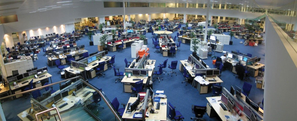
Figure 3. Open office floor plan. Courtesy of David Sim.
Therefore, the second step is to identify the structural members subjected to thermal loads based on the fire conditions. Knowing whether to account for one heated member versus several is critical in understanding how the building will perform. The location, size, and growth and spread of a fire, as a time-dependent factor in relation to various structural members, allows the engineer to know the thermal load and the length of time the thermal load is applied for both the growth and decay of the fire (structural member heating and cooling stages).
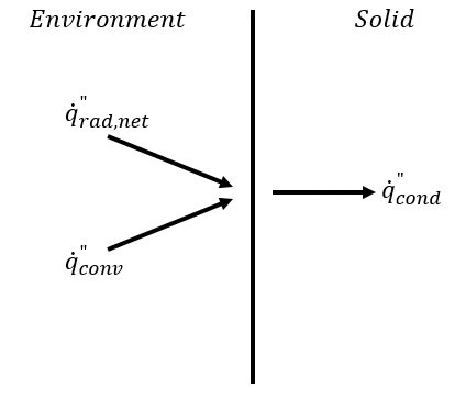
Figure 4. External thermal loads on a solid and conduction through the material.
The third step is to quantify the thermal loads and boundary conditions on the structural members. Based on the fire geometry, heat release rate, and burning conditions, an external heat flux (radiation and convection) transfers energy from the fire and/or hot gas layer to the structural member, increasing the temperature through conduction (Figure 4). The heat transfer analysis can be performed using several tools, such as simple analytical solutions for one-dimensional behavior to finite element software to account for three-dimensional behavior. Accounting for the entire duration of the fire allows for quantification of not only the heating periods (increases in heat flux) but also the cooling periods (decreasing heat flux) when the structural member decreases in temperature and contracts in size (reverse thermal expansion).
The fourth and final step is to use the member temperature output from the heat transfer analysis to determine the stresses and strains within the member due to thermal expansions and contractions and temperature strength reductions. A full structural analysis accounts for material properties, support conditions, member geometry, and full frame response of the surrounding structure. Only then can engineers and designers explicitly know the fire performance and degree of safety of the structural frame. Depending on the results of the structural and heat transfer analysis, fire protection schemes for the structural members can be recommended and implemented. Spray-on insulation or intumescent paints can be applied to structural steel to limit the increase in temperature of various critical members. The thickness of concrete cover can be increased to protect reinforcing steel and account for explosive spalling of concrete. Timber members can be increased to account for combustion and charring.
As new, novel, and emerging construction materials – such as fiber reinforced plastic and engineered mass timber – or other optimized structural solutions and designs enter the market, the need to account for fire and thermal actions within structural engineering is only increasing. Designing for the fuel loads unique to the building leads to an understanding of the safety factors of the fire protection design and, in some cases, can lead to significant cost savings by reducing or eliminating fireproofing. Knowing how a material behaves as a structural member and the correct ways to protect the structure are paramount to delivering a safe building. All of this offers not only a challenge but also an incredible opportunity for structural engineers and fire safety engineers to collaborate early in the design process and produce a truly optimized building for every potential load – seismic, wind, or fire.
Summary
Much as it is with the structural performance of buildings, the fire safety of buildings is often taken for granted, until a disaster occurs. Following a disastrous fire such as at the Grenfell Tower, shortcomings become apparent because fire has a way of finding and exploiting the weakest aspects of building fire safety design. In modern buildings, multiple fire safety systems and features are typically part of the design, so multiple failures are generally needed for a catastrophic fire to occur. However, as discussed here, building fire safety does not just happen by chance or good fortune; it requires the careful consideration of fire safety objectives, the coordination of many fire safety systems and features, and effective fire safety management over the lifespan of a building.▪
References
National Fire Protection Association. 2017. Non-Home Structure Fires, 2010 to 2015. Fire Statistics and Reports, NFPA. Web (www.nfpa.org) 4 Nov 2017.
American Society of Civil Engineers. (2016). Minimum Design Loads and Associated Criteria for Buildings and Other Structures (ASCE 7-16). Reston, Virginia. America Society of Civil Engineers.
National Oceanic and Atmospheric Administration. 2017. Significant Earthquakes (USA), 2010 to 2017. National Centers for Environmental Information, NOAA. (www.ngdc.noaa.gov). 4 Nov 2017.