
For the practicing structural engineer, deciphering the wind provisions of ASCE 7 is an ever-present challenge. However, some would argue that the real challenge is addressing commonly encountered situations which are not directly addressed in the code.
In 2011, NCSEA sent out a survey to approximately 10,000 structural engineers to generate data on the wind load provisions of ASCE 7. One of the most consistent responses was a request for more guidance on commonly encountered non-building structure conditions, such as canopies, rooftop mechanical screen walls, and solar photovoltaic panels. Because of this feedback, NCSEA provided recommendations to ASCE 7 for incorporation into ASCE 7-16.
This article discusses several common non-building structures, how they are currently addressed in ASCE 7, and provides suggestions for addressing areas where the code is silent.
Rooftop Units
Mechanical units are routinely placed on the roof of buildings. While engineers are accustomed to calculating and accommodating for the gravity loads of these units, the proper application of wind loads to rooftop units has historically been a source of confusion.
ASCE 7-05 provided an equation to generate a horizontal Main Wind Force Resisting System (MWFRS) wind load on rooftop equipment. While the commentary alluded to a high uplift component of wind loads that should be considered in the design of rooftop structures, ASCE 7-05 provisions did not provide a method for calculating this uplift.
In ASCE 7-10, the design wind force for rooftop structures was revised to include a vertical component of wind force based on research, recently completed at the time, from the University of Western Ontario. Also, a new section was added for determining the Component and Cladding (C&C) loads on rooftop structures and equipment. This section is particularly useful for engineers designing the actual mechanical equipment enclosure or its anchorage.
It is important to note that the applicability of rooftop structures and equipment provisions in ASCE 7-10 was limited to structures less than or equal to 60 feet in height. While this covers the majority of buildings designed in the United States, it does leave a significant gap for the design engineer when generating wind loads on rooftop equipment for structures over 60 feet. ASCE 7-16 removes this 60-foot limitation and allows the provisions to be used for rooftop equipment and structures on buildings of all heights.
Provisions
GC for rooftop structures.
It is understood that the wind forces on rooftop equipment and structures will be higher than those determined for wind loads on other non-roof mounted structures (ASCE 7-10 Equation 29.5-1). This increase in wind force is due to several factors:
- Due to the small size of the rooftop structure in relation to the building, there is an increased correlation between the pressures across the structure surface. In other words, there is more likelihood of the rooftop structure receiving concurrent peak pressures on the windward and leeward surfaces.
- Higher turbulence is present on the building roof.
- Accelerated wind speeds are present on the roof.
The lateral force, Fh, on rooftop structures and equipment is determined by the following equation:
Fh = qh(GCr)Af (ASCE 7-10 Equation 29.5-2)
qh = velocity pressure evaluated at the mean roof height of the building
Ar = horizontal projected area of rooftop structure or equipment
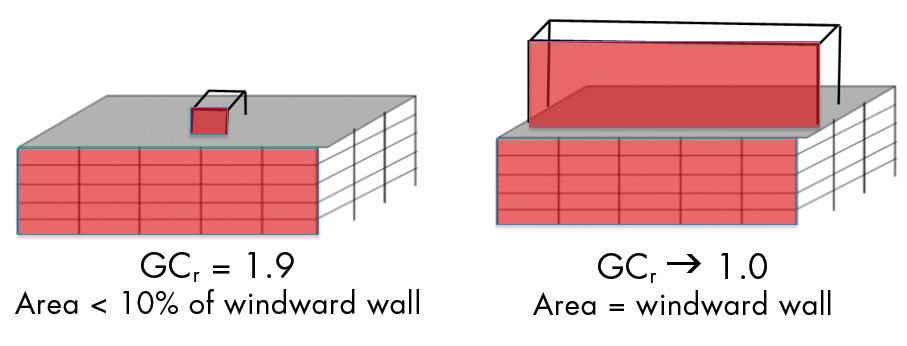
GCr = 1.9 for rooftop structures and equipment with Af less than (0.1Bh). GCr shall be permitted to be reduced linearly from 1.9 to 1.0 as the value of Af is increased from (0.1Bh) to (Bh).
The vertical force, Fv, on rooftop structures and equipment is determined by the following equation:
Fv = qh(GCr)Ar (ASCE 7-10 Equation 29.5-3)
qh = velocity pressure evaluated at the mean roof height of the building
Ar = horizontal projected area of rooftop structure or equipment
GCr = 1.5 for rooftop structures and equipment with Af less than (0.1BL). GCr shall be permitted to be reduced linearly from 1.5 to 1.0 as the value of Af is increased from (0.1BL) to (BL).
The values of GCr take into account the higher rooftop pressures, discussed above. As the rooftop equipment size grows relative to the building, the values of GCr decrease.
Rooftop Screen walls
Mechanical equipment screens commonly are used to conceal plumbing, electrical, or mechanical equipment from view. Historically, ASCE 7 has not provided guidance on what wind pressure to apply to these rooftop screens. Several approaches have been used within the industry, including applying parapet pressures, using the solid-freestanding wall provisions, and applying the rooftop structures and equipment provisions (discussed above). Little research is currently available to provide guidance for determining wind loads on screen walls and equipment behind screens.
The ASCE 7-16 commentary to Section 29.5.1 suggests that the provisions for rooftop structures and equipment be used to generate wind forces on screen walls located away from the edge of a building.
Fh = qh(GCr)Af (ASCE 7-10 Equation 29.5-2)
The commentary also alludes to the fact that screen walls located close to a building edge should be designed for parapet pressures. To quantify the appropriate distance from a building edge to differentiate between “parapet” and “rooftop structures and equipment” pressures, the boundary between corner and edge wind zones (zones 2 and 3) versus typical roof zones (zone 1) provides a reasonable delineation. Therefore, a suggested practice would be that screen walls located in Zones 2 and 3 should be designed for parapet pressures, while screen walls located in Zone 1 can be engineered for a “rooftop structures and equipment” pressure.
Research is currently underway to help advance our understanding and support updating code provisions for rooftop screen walls and the equipment behind the screens. The Insurance Institute for Business & Home Safety (IBHS) Research Center and the American Society of Heating, Refrigeration, and Air Conditioning Engineers (ASHRAE) have recently completed the first phase of a relevant study. It focused on the effects of rooftop screens on the wind loads applied to the equipment being screened. Preliminary findings suggest that fully enclosed screen wall configurations do lower wind loads on the equipment, while partially enclosed screen configurations do not provide significant wind load reduction. Also, the screen type does not significantly change wind loads on the equipment being screened. The second phase of the study focuses on the wind loads on the screen walls themselves. Results of this phase have not yet been released.
Canopies
Pressure coefficient for attached canopies.
Canopies are another example of building components that are commonly encountered by structural engineers but lack clear guidance for applying wind loads. However, even when the code lacks direct guidance, there are often ways to interpolate and extrapolate portions of the code to gain an understanding of appropriate loading on commonly encountered conditions.
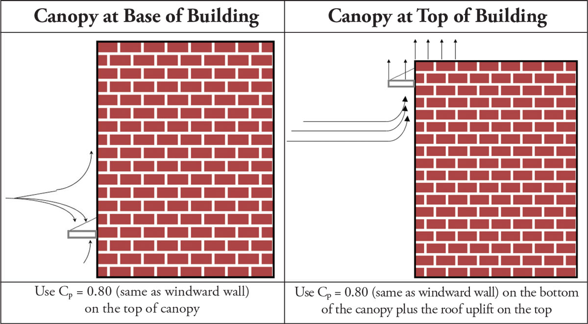
Studying and understanding Table 27.4-1, which is one of the most long-standing Tables in ASCE 7, provides an excellent basis for the design of canopies. For this instance, the most important value in Table 27.4-1 is the windward wall pressure coefficient, Cp = 0.8.
When designing a canopy, it is important to realize wind loads can act in a downward or upward direction. Depending on the location of the canopy, it is possible for either of these two load cases to control. To bound the solution, consider two extreme cases: 1) a canopy at the base of a tall building, and 2) a canopy at the top of a tall building.
For the first case, the downdraft of wind flowing down the face of the wall imposes a pressure downward on the top of a canopy (downward Cp = 0.8). For the second case, wind flows up the face of the building and applies an uplift pressure on the underside of the canopy (upward Cp = 0.8) that could combine with suction at the upper surface of the canopy.
While this bounded solution provides some guidance for the engineer, it can overestimate the total uplift on a canopy at the top of a building. Further, it does not provide direction for canopies located mid-height of a building.
ASCE 7-16 introduces a procedure for attached canopies and awnings. These provisions provide a chart to find both total downward and upward pressures on a canopy, in addition to a chart to find separate pressures on the upper and lower surfaces of a canopy. To the discerning eye, these charts yield similar pressure coefficients as the study presented above.
It is important to note that the provisions of ASCE 7-16 relating to canopies are applicable only to buildings 60 feet or less in height. It is the intent to expand these provisions in future codes to encompass canopies on taller buildings.
Tall Parapets
Exterior walls are often cantilevered beyond the roof surface to create a parapet. These parapets may serve many purposes, including fall arrest, flashing termination, fire resistance, or visual screening. In recent years, parapet heights have become increasingly taller, often to achieve visual screening of rooftop equipment. Engineers have pondered the effects of these taller parapets and whether they warrant wind load increases, decreases, and step functions. The current parapet provisions of ASCE 7 do not provide guidance on limitations or suggestions for applying wind loads to very tall parapets.
It is important to understand the history of those provisions to provide the context for the parapet provision of ASCE 7. While engineers understood that increased parapet wind pressures were a real phenomenon worthy of consideration, there were no provisions for wind loads on parapets before ASCE 7-02. In ASCE 7-02, a method for generating wind forces on parapets was introduced based on the committee’s collective experience, intuition, and judgment. In ASCE 7-05, these provisions were updated with research from University of Western Ontario and Concordia University.
There are many studies on the effects of parapets on roof wind loads, including varied parapet height. However, primarily due to instrumentation limitations, there are limited studies on wind forces on the parapet itself. For the tests that do exist, results suggest that wind loads on parapets are independent of parapet height (Mans et al., 2001).
Solar Photovoltaic (PV) Panels
The rapid rise of renewable energy has led to an increase in rooftop-mounted solar photovoltaic arrays in both commercial and residential applications. While the code has not directly addressed these solar PV panels, engineers have either forced creative implementation of ASCE 7 pressure coefficients or used Wind Design for Low Profile Solar Photovoltaic Arrays on Flat Roofs, published by the Structural Engineers Association of California (SEAOC).
The SEAOC PV committee was formed in September 2011, with the goal of addressing the lack of requirements in the code for PV systems. In 2012, SEAOC published two guides: PV1-2012: Structural Seismic Requirements and Commentary for Rooftop Solar Photovoltaic Arrays and PV2-2012: Wind Design for Low Profile Solar Photovoltaic Arrays on Flat Roofs.
ASCE 7-16 incorporates and adopts much of the work done in PV2-2012. However, SEAOC has continued to advance the solar PV guidelines and is preparing to issue PV2-2016, which will supersede PV2-2012. PV2-2016 will reference ASCE 7-16 provisions and incorporate research completed since 2012. In addition to these changes, PV2-2016 will provide updated terminology, guidance on effective wind area determination, and wind tunnel requirements. In some cases, PV2-2016 will provide recommended additional requirements where the ASCE 7-16 requirements may not be adequate.
The SEAOC PV guide covers the following Solar PV applications:
- Arrays with tilted panels on flat or low-slope roof buildings
- Parallel-to-roof (flush-mounted) arrays on sloped roofs
- Ground-mounted solar arrays
The SEAOC PV guide does not cover the following Solar PV applications:
- Roof-mounted systems with tilted panels that are not low-profile
- Arrays on other roof shapes (e.g., hip, gable, saw-tooth, etc.)
Due to rapid technological advances in the solar industry and the more extended code cycles of ASCE 7, there will be a cyclical process of adoption and modification of ASCE 7 and the SEAOC Solar PV guides. As a practicing engineer, both documents are useful for providing relevant and up-to-date suggestions for determining wind loads on PV panels.
Conclusions
There are many frequently encountered non-building structures which require design with appropriate level wind forces. As discussed above, ASCE 7 attempts to address some of these commonly encountered conditions, including canopies, rooftop equipment on buildings over 60 feet in height, rooftop screen walls, and solar PV, with future versions. Even when the code does not directly address a condition, it is important to understand the background and intent of the Code so engineers can extrapolate to find an appropriate solution.▪
Reference
Wind Loads on Parapets: Part 2: Structural and Local Cladding Loading on the Parapet Itself, C. Mans/ G. Kopp/ D. Surry, BLWT-SS37-2001/June 2001