
Historic Renovation and Seismic Retrofit
Located in San Francisco, the landmark Hibernia Bank Building recently underwent an ambitious historical renovation and seismic retrofit. First constructed in 1892, with a major addition just a few years later, the building served as headquarters for the Hibernia Bank for more than 90 years, was briefly used as a police department substation, but was then left vacant for a decade. In the late 2000s, new owner Dolmen Property Group took on the sizable task of renovating the building to allow occupancy once again. Renovations introduced improved fire safety, access, egress, and seismic safety while leaving the historically significant interiors and exteriors virtually undisturbed. Key to achieving the historic preservation objectives was reliance on the seismic resistance already provided by the massive granite and brick masonry walls that allowed the building to survive the 1906 earthquake relatively unscathed. An analytical study informed retrofit measures that surgically supplemented this seismic resistance to meet current seismic retrofit criteria. This article discusses historical background, the basis for design, and seismic retrofit techniques while illustrating the project philosophy of treating seismic retrofit and historic preservation objectives with equal priority.
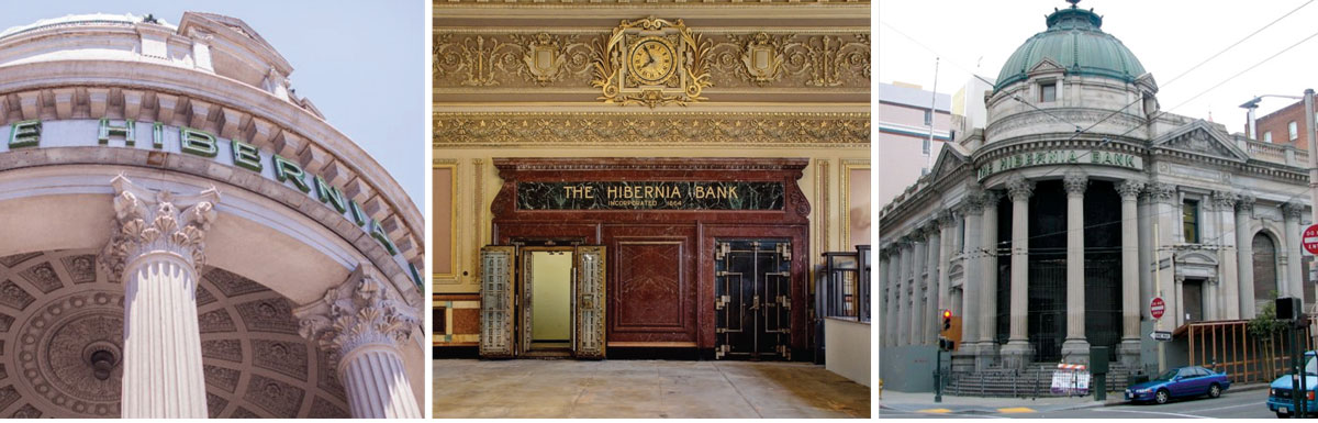
Hibernia Bank Building.
Hibernia Bank Building
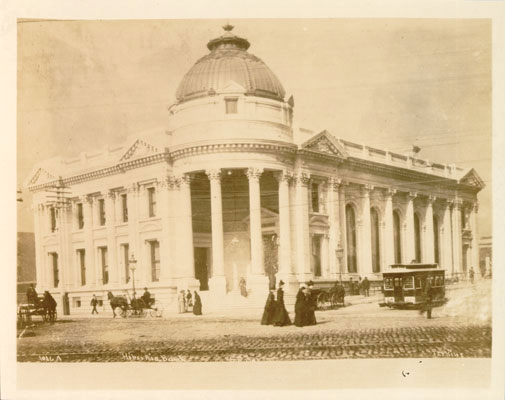
Figure 1. Hibernia Bank Building in 1894, before the addition. Courtesy of San Francisco History Center, San Francisco Public Library.
In 1889, architect Albert Pissis and his partner William Moore won a national competition for the design of a new headquarters for the Hibernia Bank at the corner of Jones, McAllister, and Market Streets (Figure 1). The building is dominated by white granite masonry, including colossal fluted granite column shafts, each cut from a single stone. It was one of architect Pissis’ first structures in San Francisco after returning from instruction at the École des Beaux-Arts in Paris, France. Other Pissis masterpieces include the Flood Building, the Emporium, and Temple Sherith Israel, all of which also survived the 1906 earthquake. The building interior is dominated by a vast banking hall with a ceiling 35 feet above the banking floor, highly detailed painted plaster, and stone finishes. The banking hall is crowned by two large skylights and matching ceiling level laylights (Figure 2). Two stories of luxury offices are located on the McAllister Street side.
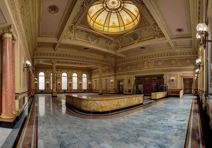
Figure 2. The Hibernia Bank Building main banking hall with banking counters and stained glass laylights overhead. Courtesy of Bruce Schneider.
The building is generally rectangular in plan, with dimensions of approximately 130 feet by 120 feet (Figure 3). The primary vertical elements of the structure include four massive perimeter unreinforced brick and granite masonry bearing walls and massive interior brick walls. The roof system uses long-span steel trusses, steel purlins, and a concrete slab. The floor system uses cast concrete topped brick arches supported on steel beams.
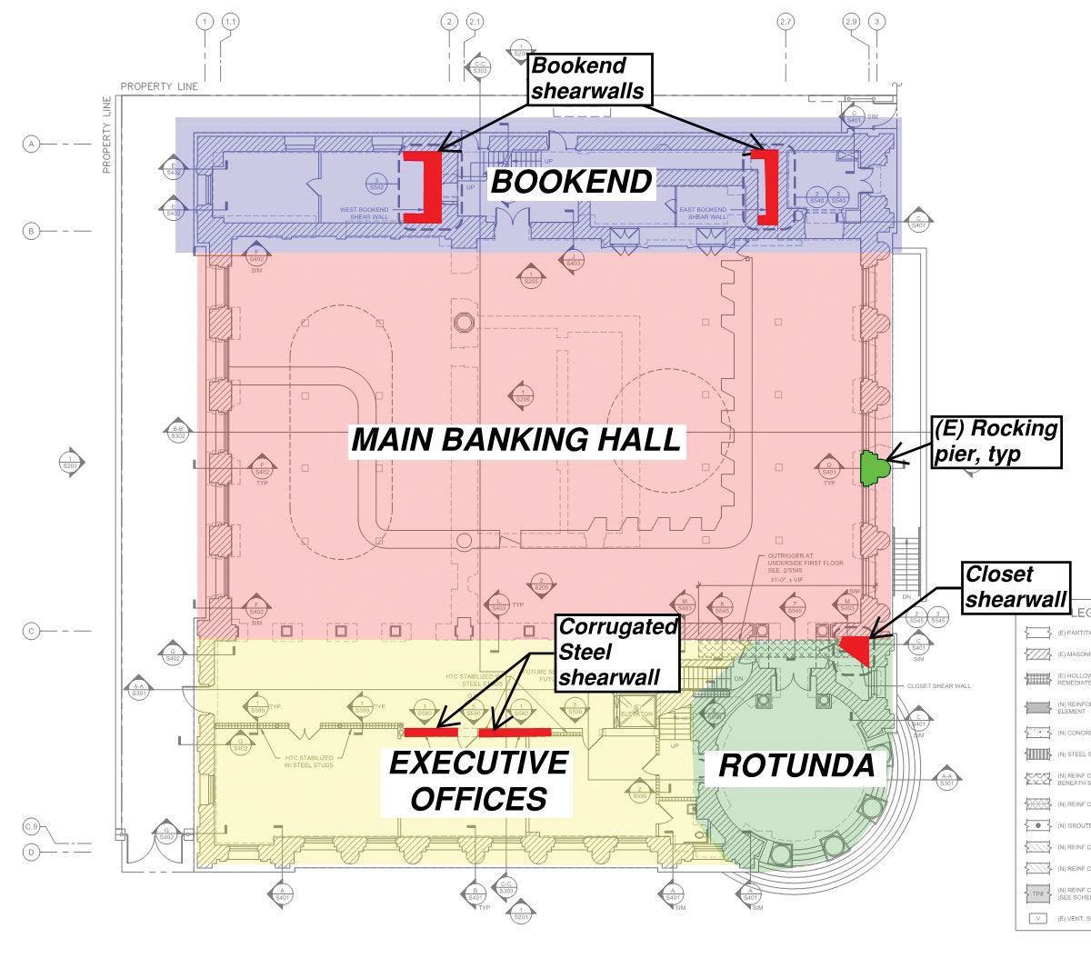
Figure 3. Hibernia Bank Building floor plan with shaded masonry walls. Diagonal hatched walls are of combined granite and brick masonry.
Available reports, including a 1906 U.S. Geological Survey report, and photographs suggest that the building survived the 1906 earthquake with little earthquake damage, but with damage from the following fire. Using information on performance and estimated ground shaking intensities from the 1906 earthquake, the design team ran analytical studies that corroborated the observed good behavior. Key to this behavior was the existing massive masonry walls that served to limit drift to modest levels in spite of the tendency towards torsional response (Figure 3). These indications of good seismic performance, combined with the adopted historic preservation objectives, were the primary justification for a focused, surgical seismic retrofit approach.
Basis for Design
The historic structures report identified the vast majority of the interior and exterior of the building as “very significant.” The Secretary of the Interior’s Standards for Treatment of Historic Properties, a primary national guideline for historic preservation work, calls for work such as this to “…make possible a compatible use for a property … while preserving those portions or features which convey its historical, cultural, or architectural values.” Attention to the preservation of historic fabric and maintenance of character-defining features were thus determined paramount in guiding the retrofit solution.
The era when a building of this size could economically function as a retail bank has long since passed. Therefore, the owners directed that the building renovation maximize potential future occupancy while meeting historic preservation objectives. This combination barred the banking hall from being broken into smaller rooms, implying Group A assembly occupancy. This potential change from the historic Group B occupancy triggered the structural evaluation of gravity load systems. At the same time, the potential occupant load in the main banking hall implied Occupancy (Risk) Category III. It was also identified that the building had not undergone evaluation or retrofit in response to San Francisco’s 1992 unreinforced masonry building (UMB) ordinance.
The resulting range of work dictated use of a variety of building codes, each relevant for some portion of the work. Use of the 2010 California Historical Building Code (CHBC) is permitted by California state law for determining code criteria for a wide range of work on eligible or designated historic structures, and so was used as the primary starting point. Following the CHBC criteria, gravity systems were checked for live loads consistent with the new occupancy. Following the CHBC and the 2009 and 2012 editions of the International Existing Building Code (IEBC), seismic retrofit minimum criteria were set and were verified to meet the intent of the 1992 UMB ordinance. The CHBC and the 2010 San Francisco Building Code (SFBC) criteria included remediation of the hazard posed by the hollow clay tile (HCT) walls located along exit paths. The new structure, including extensive new egress paths, was designed in accordance with the SFBC. The CHBC provides broad discretion for the use of alternate materials and methods of construction provided that they meet the intent of the CHBC, in recognition of the special conditions encountered in dealing with archaic materials and construction. Based on this, several alternate methods of construction were identified for this project, ranging from a study of adhesive anchors in granite stone masonry to center core systems and beyond. The applicable codes and methods of construction were explained in a basis of design document that was vetted with the building department.
A number of available standards and guidelines were consulted during the design of the seismic retrofit. With design forces remaining in the near-elastic range to protect the masonry, the retrofit is very much in keeping with the spirit of the ASCE 41 linear elastic procedures. Full application of ASCE 41 procedures, however, would have relied on analytical studies of very limited accuracy and benefit. This speaks to the need to maintain the provisions of the CHBC to provide a seismic retrofit basis for buildings with archaic materials and systems that are beyond the testing and numerical quantification basis of ASCE 41 and similar methodologies.
Seismic Retrofit Techniques
Retrofit measures for the primary seismic force-resisting system focused on improved strength and connectivity of the existing roof diaphragm and wall systems. The minimum seismic base shear for evaluation and retrofit used a seismic response modification coefficient (R-factor) of 1.5. As a result, the primary structural elements, both existing and new, are anticipated to stay in a near-elastic stress range with very limited deformations. The following is an overview of seismic retrofit techniques used.
Roof Strengthening
Around the perimeter of the building, granite balustrades were temporarily removed to permit installation of reinforced concrete bond beams. The bond beams strengthen the walls by preventing the propagation of cracks to the free edge of the masonry and act as chords and collectors for the roof diaphragm. The bond beams also serve to anchor the tops of the wall center-cores and as anchorage points for roof-to-wall ties. A number of similar reinforced concrete members were provided to serve as chords and collectors within the interior of the roof. To provide a connection between the bond beams and the existing concrete roof diaphragm, and to create continuity between adjacent roof segments, a pre-tensioned “tie plate” was cast over each roof diaphragm segment along its perimeter. The interface was pre-compressed with regularly spaced pre-tensioned bolts and steel plates, providing a zero-slip shear friction connection between the existing roof diaphragm and the bond beams. A carbon fiber reinforced polymer (CFRP) system was used to complete the roof strengthening. Surface-mounted CFRP sheets were installed at the top of the slab. Near-surface-mounted CFRP rods were provided around the perimeter and at openings in the diaphragm for chord strengthening and crack control. Additional surface-mounted sheets were provided on the bottom of the roof slab with through-thickness CFRP anchors to basket high-stress regions and protect against falling hazard from isolated pieces of roof diaphragm, should localized degradation occur during an earthquake.
Concrete Shear Walls
Although the structure has several massive masonry shear walls, the analytical studies identified the need to add a limited number of strategically located new shear walls. One such location is on the north side of the building where a pair of massive parallel masonry walls, only twelve feet apart (the “bookend” in Figure 3), provide significant north-south seismic mass which could be detrimental to the seismic response. To turn this negative attribute into a benefit, the walls were interconnected with reinforced concrete “web” shear walls such that the entire system resists loads as a vertical box girder cantilevering from the basement. Another strategically placed reinforced concrete wall was located in a closet near the entrance to the building.
Center Cored Wall Reinforcement
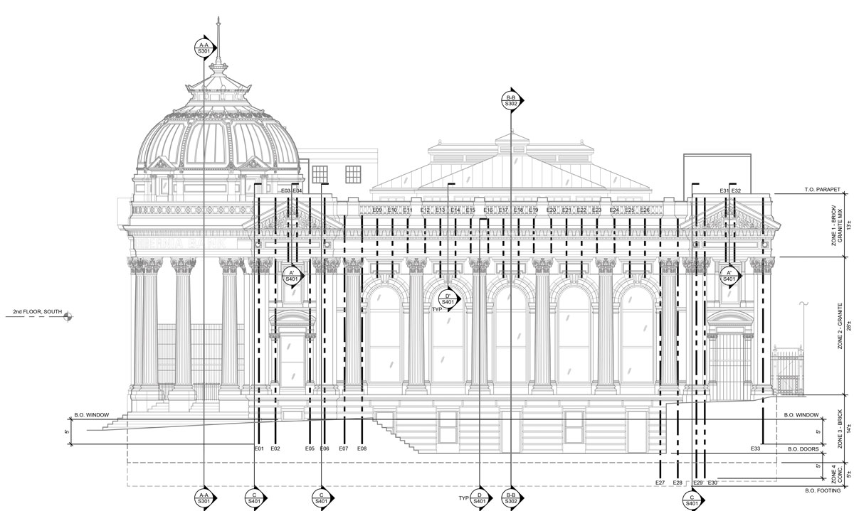
Figure 4. Center coring at Jones Street elevation. Heavy dashed lines indicate center core location and extent.
Center coring of the granite and brick masonry walls and piers was included to provide general connectivity and limit slip in masonry joints. The retrofit involved the coring of holes, installation of high strength steel rods as reinforcing, and grouting with a high-strength, low modulus polyester resin-based grout custom designed to reduce shrinkage and heat build-up during curing. The center coring of walls for this project was more difficult than usual due to the unpredictable mix of brick masonry and much harder granite masonry over the height of each core. Figure 4 shows center cores on one of the exterior wall elevations.
Corrugated Sheet Steel Shear Wall
A secondary lateral bracing system was desired in the executive office wing, but the presence of highly significant finishes presented difficulties. A corrugated sheet, steel shear wall was selected because its relatively high capacity at low drift levels and moderate capacity at larger drift levels provided the best combination of deformation compatibility and control of load path.
Hollow Clay Tile Wall Stabilization
In the repairs following the 1906 earthquake, wood partition walls throughout the building were replaced with single-wythe or double-wythe hollow clay tile (HCT), chosen for its “fireproof” properties. The behavior of such unreinforced, ungrouted HCT masonry in an earthquake, however, is usually quite poor, so increased out-of-plane stability was required along paths of egress, without damaging significant finishes. In locations with significant finishes on one face, cold-formed steel (CFS) stud walls were installed alongside the opposite face, and the CFS and HCT walls interconnected with fasteners on a close on-center spacing. In locations with significant finishes on both wall faces and where access was available at the top of the wall from the attic, the HCT was drilled over the full height using segmental drilling equipment to provide a clear vertical chase for installation of vertical reinforcement and grout.
Conclusions
Over one hundred years after the Hibernia Bank Building survived the 1906 earthquake with little structural damage, the building has undergone an extensive historic renovation and seismic retrofit, making it eligible for a range of new uses. Pivotal from a structural standpoint was the time taken to understand the inherent positive seismic characteristics of the building, and use of the California Historical Building Code framework for legal recognition of alternate materials and construction.
Acknowledgements
The authors would like to acknowledge and thank owner Dolmen Property Group, contractor Landmark Construction, project architect Elevation Architects, and geotechnical engineer Rollo and Ridley. In addition to the authors, the WJE team also included engineers Jeff Rautenberg, Kari Klaboe, and Jason Porto, as well as historic preservation architect Alan Dreyfuss.▪
References
VerPlanck C, Kelley T (2009): Hibernia Bank Building Historic Structures Report, Kelley & VerPlanck Historical Resources Consulting, LLC, San Francisco, California.
United States Geological Survey (1907): The San Francisco Earthquake and Fire of April 18, 1906, and their Effects on Structures and Structural Materials, Department of the Interior, Washington, DC.
U.S. Department of the interior (1995): Secretary of the Interior’s Standards for Treatment of Historic Properties, U.S. Department of the Interior, National Park Service, Cultural Resource Stewardship and Partnerships, Heritage Preservation Services, Washington, D.C.
California Building Standards Commission (2010c): California Historical Building Code, California Code of Regulations Title 24, Part 8, California Building Standards Commission, Sacramento, CA.
International Code Council (2009, 2012): International Existing Building Code, 2009 and 2012 Editions, International Code Council, Country Club Hills, Illinois.
San Francisco Building Code (2010): San Francisco Building Code, 2010 Edition, San Francisco Board of Supervisors, San Francisco, California.
Seismic Evaluation and Retrofit of Existing Buildings, 2013 Edition (ASCE 41-13): American Society of Civil Engineers, Reston, Virginia.
Stojadinovic B, Tipping S (2008): Structural Testing of Corrugated Sheet Steel Shear Walls. Proceedings of the Nineteenth International Specialty Conference on Cold-Formed Steel Structures, St. Louis, Missouri.