
Heavy snow accumulations on the roof of an elementary school in central Oregon in January 2017 caused structural damage to six wood roof trusses that span approximately 75 feet. The trusses were found to have some bolted connection failures at heel plates, as well as three split and fractured web elements also associated with their bolted connections. Snow load on the roof was reportedly around 40 pounds per square foot (psf), while the trusses were initially designed for 30 psf. Despite the significant snow load imposed on trusses with compromised heel connections and fractured web elements, they did not collapse or exhibit excessive deflection. After an initial assessment in January 2017, other engineers designed and directed temporary repair and stabilization for the trusses to allow for continued occupancy until a permanent repair could be determined and implemented.
The original design of the trusses used glued laminated (glulam) timber elements for top and bottom chords and web members, with steel gusset plates and large (1¼-inch diameter) bolts to connect the wood elements. The trusses were designed initially per the 1970 Uniform Building Code (UBC) and constructed and placed into service around 1973. Each of the six trusses had limited prior repairs, designed and implemented in 1981, to address splitting of the wood elements near the large bolts.
From the 1970 UBC through the 1986 National Design Specification® for Wood Construction (NDS®), provisions existed to design 1¼-inch diameter bolted wood connections. Starting with the 1991 NDS and still today, provisions are only provided for maximum bolt diameters of 1 inch. This code change was made following reported field problems with larger diameter bolts, and the results of research conducted in the 1980s that showed large diameter fasteners could induce perpendicular-to-grain stresses in the wood that can lead to the wood splitting before the expected bolted connection load carrying capacity can be reached.
Other engineers and the school district expressed concerns that the large diameter bolted connections were inadequate, as demonstrated by their performance that led to repair in 1981 as well as the performance problems found in January 2017. Other engineers had advocated for complete removal and replacement of the trusses, whereas the authors opined that the trusses were repairable. Due to the skepticism expressed by others that the trusses were indeed repairable, the authors suggested that, in addition to the customary structural engineering calculations demonstrating adequacy, full-scale load testing could also be performed to prove that the repaired trusses were capable of sustaining required design loads. Wiss, Janney, Elstner Associates, Inc. (WJE) was hired by the school district to design repairs to the trusses, conduct full-scale load testing, and perform structural observations during construction. Repairs were designed to address physical damage due to the load imposed on the roof as well as to provide upgrades to mitigate the potential splitting problems known to occur from the large diameter bolts.
Analysis and Repair Design
Structural analysis of the trusses was made to determine load effects in truss elements, including bolted connections, when subject to design loads. Allowable stresses for the 1973-era glulam elements were taken from the 1970 UBC, the code in effect when this material was installed. Also, and for reference purposes, allowable stresses were “converted” to a contemporary equivalent and also checked against design load demands.
The following approach was used to determine an allowable design capacity for the bolted connections:
- Calculate the capacity per the 1986 NDS. This represents the most relevant NDS with provisions for bolts larger than 1-inch in diameter.
- Calculate bolt row tear-out following the 2015 NDS Non-Mandatory Appendix E for determining Local Stresses in Fastener Groups. This applies to tension connections only.
- Upon review of AITC Technical Note 8, Bolts in Structural Glued Laminated Timber, and detailed review of its three references, assign an empirical adjustment factor based on the referenced testing to reduce the 1986 NDS calculated capacity.
- Select an allowable bolted connection design value based on the lower of item 2 or item 3.
The glulam elements themselves were found to be within allowable limits when subjected to the design loads. A number of bolted connections were found to have demands that exceeded the capacity. Where demands exceeded allowable capacity, an improvement was designed to resolve the overstress condition. The locations with the largest overstress corresponded to locations with observed physical damage, confirming the model results. Based on the analysis, there were two general groupings of outcome and repair approaches:

Excerpt from design drawings for added HeadLOK screws placed around existing bolts to clamp wood and resist splitting.
- Where design demands exceeded allowable bolted connection capacities from 1% to 30%, then supplemental HeadLOK timber screws by FastenMaster were added around the bolted connection to resist potential tension perpendicular-to-wood-grain splitting induced by the large diameter bolts. The HeadLOK was chosen for its small diameter shaft (0.19-inch), large diameter head (0.625-inch), and short thread length (2-inch). The small diameter shaft does not promote splitting and the large head separated from its threads by several inches serves to clamp the glued wood laminations together. The capacity of wood to resist tension perpendicular to grain is so low that there are no allowable design values. Assuming allowable tension perpendicular grain stress is equal to allowable radial tension stress to represent capacity, the analysis shows the supplemental HeadLOK more than doubled or tripled, depending on location, the ability to resist tension perpendicular-to-grain splitting in the plane of the bolts.
- Where design demands exceeded allowable bolted connection capacities by more than 50% (there were no results between 30% and 50%), steel plates were added to bypass the original bolted connection. This occurred at all truss heel connections and all first truss verticals inward of the heel. This new steel plate was bolted to the existing steel gusset plate using AISC 360-10 Specification for Structural Steel Buildings design provisions and screwed to the existing wood using Simpson Strong-Tie SDS screws.
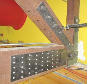
New heel plate connection at the bottom chord and supplemental HeadLOKs installed on the diagonal bottom surface.

In addition to the analysis and calculations that demonstrate the adequacy of the repair, load testing was also performed.
Load Testing
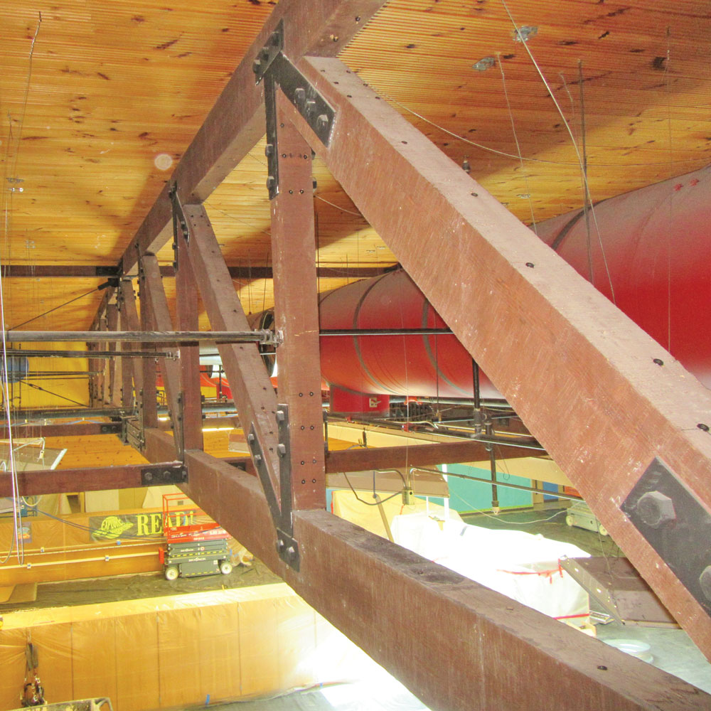
Repaired truss.
Upon completion of repair of the first truss, load testing was performed to verify the efficacy of the repair before advancing the same repair on the remaining five trusses. The load test protocol was developed based on ASTM E196-06, Standard Practice for Gravity Load Testing of Floors and Low Slope Roofs, and ANSI/TPI 1-2014 Appendix B, Proof Load Tests For Site-Selected Trusses. The load test consisted of applying specified test loads via water filled pools placed on the roof to impose a load on the truss. The truss was then monitored for any signs of distress and was instrumented to measure deflections due to imposed loads. The evaluation criteria included a limitation on the maximum truss deflection. A second criterion was a limitation on the maximum residual deflection after unloading the structure, i.e., rebound. Finally, the portion of the structure tested was to show no evidence of failure.
The maximum superimposed test load was the 30 psf roof snow design load which, when applied over the tributary area of the truss, equates to 30,453 pounds. The total weight of water needed for the test was then determined to be equal to the snow load (30,453 pounds) plus removed ceiling tiles and their metal support grid (1,493 pounds) minus the pool self-weight (215 pounds). The total weight of the created load was 31,731 pounds, which equates to 3,805 gallons of water.

Pools filled with water on the roof during load test of the repaired truss.
The loading method used five premanufactured 870-gallon capacity wading pools with approximate dimensions of 118 inches by 79 inches by 26 inches deep. Since the five pools were to place the load in discreet “patch” locations over the span of the truss rather than the idealized uniform snow load, an analysis was made of pool placement to most closely match load effects from uniform loading. The total weight was divided equally into the five pools. The contractor fabricated a five-part manifold using PVC pipe, fittings, and valves to control the amount of water added to each pool. The pools were filled using a hose from a water truck to the manifold. Amounts of water in the pools were distributed by monitoring the gallon flow meter and measuring water depths in the pools.
As a precaution, post shores were installed below the tested truss, which extended to the concrete slab-on-grade floor. The post shores immediately below the truss were installed such that there was a gap to allow for truss deflection during the load test. The load was applied in four stages representing 25, 50, 75 and 100% of the test load. The final test load was kept in place for six hours. Deflection measurements were made using cable-extension transducers (string pots) anchored to the floor and extended to the bottom of the truss. Maximum deflection at the center of the truss from testing was 0.825 inches, which equates to about L/1090 and was significantly less than building code-allowable deflections.
The repaired truss passed the load test by meeting both the maximum deflection criteria and the residual deflection criteria and had no distress or failure during the test.
Summary and Conclusion
Repairs were designed to address wood splitting failures and deficiencies associated with large diameter bolts in a truss. New steel plates were added in strategic locations, as were self-drilling small diameter screws around the bolted connections, to clamp the wood around the bolts and reduce the potential for the wood to split due to stress imposed by the bolt. As part of the repair process, the repair was implemented on one truss and proof load testing was conducted to demonstrate the repair could resist the full design load. Approximately 32,000 pounds was placed on the roof via water filled pools over the truss and held for six hours. Truss deflections were monitored during testing and after to record the recovery. The truss passed the proof load test and similar repair was then implemented to the other five trusses. The repair approach used a novel method to reinforce around larger diameter bolts to substantially improve their capacity. The repair saved significant time and money over the full replacement option that was also considered.▪