
Tree House Sequence, HD BIM, and PBEE
Hollywood Casino Jamul (HC Jamul) is a three-story entertainment facility, located in Jamul, California, with approximately 200,000 square feet of gaming, restaurants, and lounges atop an eight-story, below-grade, 1,800-space parking garage. The casino structure’s innovative steel lateral force resisting system utilizes rocking braced frames and Krawinkler fuses integrated into Vierendeel trusses to produce a performance-based seismic design. This keeps the integrity of the perimeter cantilevered gravity system protected while the lateral system is repairable after a major seismic event.
The parking garage is a post-tensioned concrete slab system built using an unconventional construction sequence. The casino steel structure construction was prioritized ahead of the garage structure underneath it, to compress the overall construction duration and accelerate the completion of the design-intensive casino interior.
A single High Definition Building Information Model (HD BIM), developed in Tekla Structures, was used from conceptual design to construction documents, and finally to shop drawings.
 Construction Sequence Structural Concept

The concept was first to erect the steel casino structure, supporting it on concrete stair and elevator cores and 90-foot tall steel “stilts” that would eventually become encased in the final concrete garage columns. The final columns would be founded on conventional spread footings bearing on rock.
During construction, a temporary lateral system supported the casino and provided anchorage for tension ties that braced the columns against buckling. Casino elevators and escalators would be installed with the steel. MEP, roofing, and exterior closures would be completed and theming underway when there were still months to go on the construction of the seven 550-foot by 220-foot, below grade post-tensioned concrete slabs.
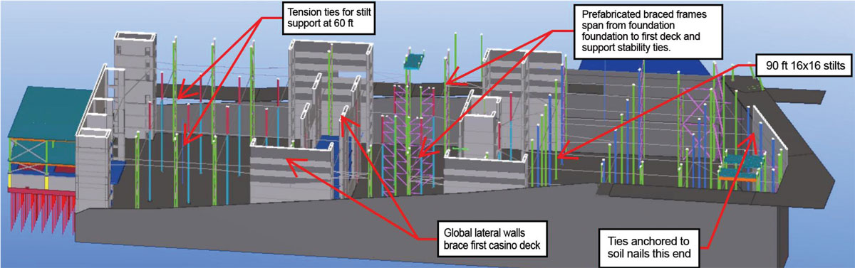
Figure 2. HD BIM model of 90-foot tall early walls.
Contractor Selection
The sequencing was established to build the casino structure first. Then, the eight-story parking garage would be brought up while the intensive build out of the architectural theming, finishes, and MEP systems on the inside of the casino were put in place. A set of schematic design documents based on this concept was issued in October of 2013 and used to solicit proposals from three general contractors. The ability of the contractors to collaborate with the design team in fleshing out the details of the final design, based on cost and schedule evaluations, was paramount in the selection process.
A general contractor team composed of Rudolph Libbe, an Ohio-based contractor who had previously worked with this owner and had participated in a previous HD BIM project with the design team, and C. W. Driver, a Southern California general contractor familiar with the local sub-contractor market, both embraced the concept and brought their own ideas to the interview. They were selected to team with the Jamul Indian Tribe, Penn National Gaming, and the rest of the design team to deliver the project. The contractor estimated that the proposed sequence had potential to save seven months on the schedule.
With coordination and input from the general contractor, all temporary conditions from the start of construction to completion were included in the structural design.
Excavation and Retention System
The excavation varied from 90 feet deep on one end to 30 feet deep on the other. The material consisted of weathered granite bedrock that ranged with depth from soft to very hard. A soil nail wall, designed by an independent engineering firm, provided permanent support for the excavation and was eventually tied to the permanent structure so that the two worked together. Excavation commenced in early 2014 with the anticipation that the bulkhead walls would take at least one year to complete; at that time, the design of the casino was still at a schematic design level.
The project scheme envisioned that, during excavation activities, the steel structure could be designed and detailed so that steel erection would commence as soon as the foundations were in place. The plan was to use steel braced frames for the “tree-house” lateral system and encase them in concrete walls within the garage construction. The excavation proceeded faster than expected through the summer of 2014; however, the casino design evolved more slowly than anticipated. A strategic decision was made to change the temporary steel lateral system to permanent concrete walls so that there would be no lag time if the excavation was completed early.
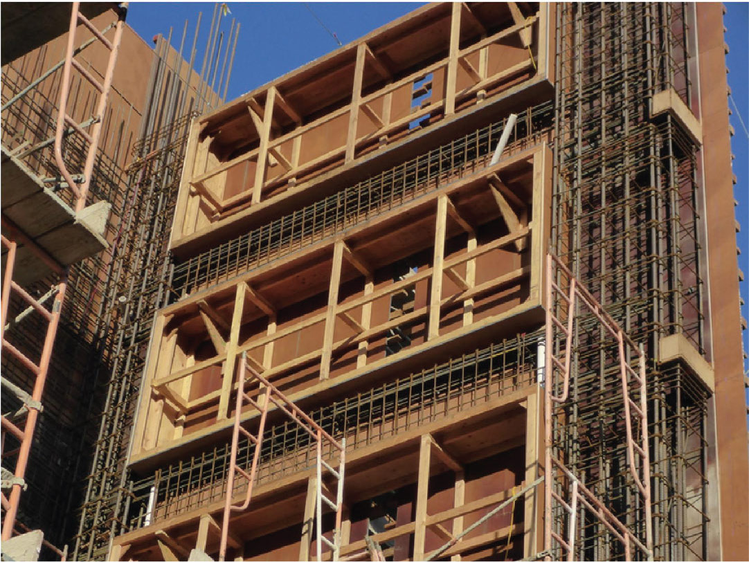
Figure 3. Prefabricated rebar cages and shotcrete forms for early walls.
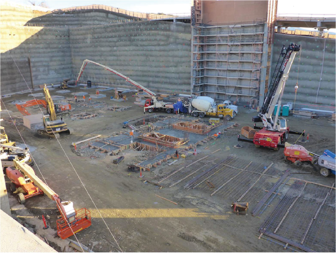
Figure 4. View of the site during early wall construction.
Early Wall Construction
The buttress walls were constructed to a height of approximately 90 feet using shotcrete. They were designed for wind loads in the freestanding condition, and to carry seismic and wind loads for the completed casino structure without help from the garage slabs. The walls are founded on grade beams that mobilize sufficient dead load to resist overturning in temporary conditions.
In the final building, the early walls are incorporated into the overall foundation walls, stair and elevator cores, and ramps. The ramp slabs had to be constructed early to mobilize out-of-plane frame action for wind resistance in addition to temporary guy cables. The reinforcing steel was designed to be prefabricated into cages, with details such as straight dowels that could be loosely tied in the link beam cages. This was done so that the development length of reinforcing steel could then be slid out into the columns. This level of detail was incorporated into the HD BIM model to decrease labor and increase safety.
Tree House Columns and Framing
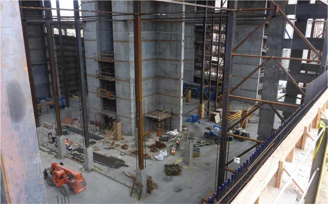
Figure 5. View of the site with early walls, stilt columns, and tension ties.
The main casino floor and the office area above were framed with 30-foot by 60-foot bays using W27x84 and W30x99 beams on 10-foot centers spanning to W30x116 girders. 16-inch square box columns were used for the temporary condition to fit within the planned 28- by 28-foot module concrete columns supporting the eight-story parking structure. These box columns would support the full weight of the Casino structure 90 feet in the air. After much discussion, it was decided to design the columns for the full dead load of the superstructure plus a 20 pound per square foot construction live load over all floor and roof areas. The columns were designed with a fixed base condition and a single level of bracing at the 7th garage floor, approximately 60 feet above the foundation.
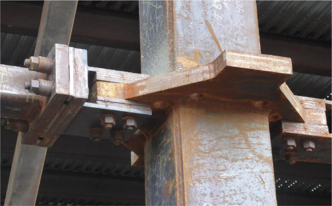
Figure 6. Tension tie connection.
Each column was braced by HSS6X4 tension ties at approximately 90 degrees and placed flatwise at the center of the 10-inch thick post-tensioned slab. The tension ties were supported at mid-span by sag rods to the floor framing (Figures 5, 6 and 7). The connections at the columns allowed the HSS members to be offset by one-inch vertically from each other to accommodate the slab reinforcing and post-tensioning strands in orthogonal directions so the HSS tension ties would not need to be removed. (After all this planning and design, the contractor decided that it was less effort to cut the tension ties after the slab at the 6th floor was tensioned.)
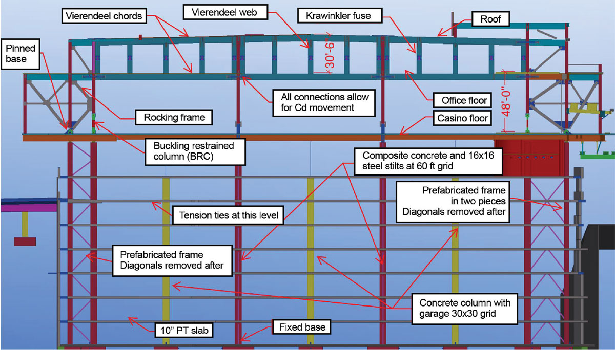
Figure 7. Section through HD BIM with key elements.
The tension ties were supported on either side of the building by 10-foot-wide shop fabricated frames that spanned from the foundation to the first casino diaphragm 90 feet above. These were designed in accordance with AISC stability requirements for stiffness under theoretical loads. The diaphragm was supported for all lateral loads by the primary lateral system formed by the early walls.
All elements of the temporary system were part of the structural design, coordinated with the contractor, and included in the HD BIM.
Performance-Based Earthquake Engineering
The project is in an area of moderate seismicity, with SDS = 0.63, SD1 = 0.22, and classified as site Class B. An importance factor of 1.25 was used, with R equal to 6.0 and a Seismic Design Category D. The calculated base shear was 3,068 kips.
One of the greatest design challenges was solving the soft-weak story discontinuity created by the open 25-foot-tall casino level. The design allowed for limited areas for seismic bracing around the perimeter, as opposed to under the 15-foot-tall office level which could be braced extensively.
The lateral system evolved into a robust and elegant performance-based design utilizing a top-down arrangement of in-line yielding Vierendeel trusses and rotating (as opposed to rocking or racking) buckling restrained braced (BRB) frames, with true pinned bases, in parallel. The Vierendeel trusses pull the overturning moment to the top of the frame which, in turn, enforces a uniform first mode response. Krawinkler fuses at mid-height of the Vierendeel verticals are used to tune the pushover curve. Krawinkler fuses are steel plates with diamond-shaped cutouts that provide substantial shear strength, a predictable yield force that mobilizes both shear and flexural yield, stable hysteresis loops, and disproportionate displacement capacity.
The system configuration utilizes rather narrow braced frames that have a true pinned connection on one leg, allowing the entire frame to rotate about the base. The rotation is prevented by coupling the frame to the Vierendeel truss system at the office level above the casino. The shear that can be carried by the Vierendeel trusses is limited by the use of fuses at the mid-height of the members. A vertical BRB is used in place of the 2nd column in the braced frame. The forces in the system are limited by the capacities of the BRB column and the Krawinkler fuses.
Structural Analysis and Detailing
State-of-the-art pushover analyses were used to assure that the structure can reach 150% of the displacement demand in the maximum considered earthquake without any calculated inelastic demand in the primary structure. The energy demands of the earthquake are absorbed in the designated fuses – the butterfly plates and the BRB columns and braces.
Target displacements in a Maximum Considered Earthquake (MCE) are determined by performing nonlinear analyses on a single-degree-of-freedom system that has the height, frequency, and backbone push-over curve of the subject building through a suite of time histories scaled to the seismicity at the site. Target displacement for the Jamul structure was about 3.5 inches. Analysis showed all frames in the Jamul structure can accommodate significantly higher drifts than the target displacement at MCE, without inelastic action in the non-fuse framing.
The special connections associated with this system are the collector connections that jump the columns at the top and bottom of the Vierendeel trusses. These are required to isolate the gravity columns from the inelastic deformations of the butterfly fuses that result in an offset between the top and bottom Vierendeel chords.
Once a structure with an acceptable nonlinear performance was developed, it was analyzed in ETABS using a response spectra approach and checked for code compliance. The structure is designed to conform with all code provisions up to code level forces, after which the designated fuses yield.
HD BIM
The objective of the structural design process within the High Definition Building Information Modeling process is to deliver a complete design that incorporates all fabrication and erection constructability considerations in a single Tekla model. The HD model is shared in the cloud with all project participants and used to produce shop drawings. This step eliminates the traditional Remodeling/RFI/Shop Drawing (RRSD) process that is the source of so much paperwork and so many delays in a typical construction project.
The HC Jamul HD BIM includes structural steel, cast-in-place concrete, reinforcing steel, precast concrete, masonry, stairs, and metal deck.
The construction documents, structural steel detailing, rebar detailing, and stair/miscellaneous steel detailing were all completed in the same cloud-based model. Approximately 4,200 tons of structural steel (6700+ drawings), 2,300 tons of rebar (400+ drawings), and 18 stairs (400+ drawings) were detailed in the Tekla model. Tekla technologies enabled the complete and continuous involvement of the SEOR, improving the construction efficiency, economy, and quality of the project. Many International Foundation Class (IFC) reference models were used for project coordination between different design disciplines and subcontractor trades, reducing costly coordination errors.
The model included stairs and all temporary structures and bracing required for the non-standard construction sequence. The complete HD BIM for concrete, reinforcing steel, and structural steel, including all temporary structures, won the Tekla North American BIM award. Projects like this put the profession on the path to 21st-century processes.
A Strong Team
The Hollywood Casino Jamul facility celebrated a soft opening on July 30, 2016, and a grand opening in October 2016. That represents a short three years from concept release and RFP for contractors to completion, a feat accomplished by early contractor involvement, an unusual but effective construction sequence, and the use of HD BIM.
Collaborative teamwork and problem-solving characterized the project team without which the project could not have succeeded.
- GPLA – SEOR and structural team leader responsible for HD BIM modeling in Tekla, lateral concept development with Exponent, gravity design, design of post-tensioned slabs, temporary garage support system, rebar detailing, and stair detailing.
- Exponent – Responsible for collaboration on concept development, seismic pushover analysis in MASTAN, global lateral analysis in ETABS, and peer review of design execution.
- Detailing Group – Responsible for producing steel shop drawings from cloud-based Tekla model.▪
Project Team
Owner: Jamul Indian Tribe
Structural Engineer of Record, Steel and Rebar Detailers: Gregory P. Luth & Associates
Development and Operations Manager: Penn National Gaming
Design Architect and Architect of Record: Marnell Architects
Peer Review and Structural Analysis, Casino Structure: Exponent
Shop Drawing Production from Cloud-Based Model: Detailing Group
SEOR Permanent Soil Nail Retention System and Three Site Bridges: Pirooz Barar & Associates
General Contractor: CW Driver
Structural Steel Fabricator: Rossin Steel
Structural Steel Erector: Asbury Steel
Concrete Sub: J T Wimsatt
Rebar Fabricator and Placer: CMC
Tekla Structures: HD BIM Software