
Located on Ford Island at Joint Base Pearl Harbor-Hickam in Hawaii, Building 26A was constructed in 1935 for an aviation storehouse and an airplane hangar for the Navy’s Fleet Air Base. The facility survived the December 7, 1941, surprise attack on Pearl Harbor (Figures 1 and 2) and in the 75 years since has undergone several changes in use. In 2014, the Navy elected to convert Building 26A into a new training facility for the Center for Security Forces (CENSECFOR).
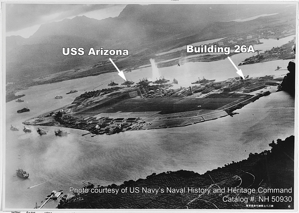
Figure 1. Pearl Harbor under attack on December 7, 1941, taken by a Japanese plane.
This conversion included repairing exterior deterioration and upgrading the structure to meet current seismic, hurricane, and antiterrorism criteria. A design-build team led by Hensel Phelps was awarded the $15.1 million contract to update the historic building.
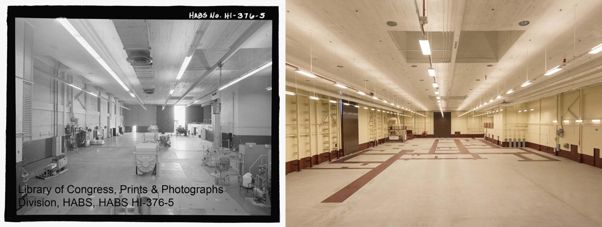
Figure 2. Building 26A original interior (left) and current interior (right).
Building 26A consists of 30,000 square feet of open, double-height space and 15,000 square feet of adjacent two-story office and support space. The primary structural system in the open bay consists of long-span steel trusses supporting steel purlins and tongue and groove plywood sheathing. The trusses are supported at each end by steel columns encased in concrete. A three-inch-thick ultra-lightweight concrete ceiling with embedded support steel is suspended from the steel purlins, primarily for fire protection. In the office area, the structure consists of concrete-encased steel beams and columns supporting cast-in-place floor and roof slabs. The building is enclosed by ungrouted masonry walls and the foundations consist of shallow spread footings.
The renovation presented several unique structural challenges, including:
- Analyzing and strengthening the antiquated unreinforced and ungrouted exterior masonry walls for resistance to current wind, seismic, and blast loads.
- Ensuring structural modifications would preserve the building’s distinctive historical design features.
- Determining existing conditions and documenting modifications made during numerous renovations over the previous 75 years.
- Addressing prevalent structural deterioration, such as corroded steel members, rotted plywood roofing, and cracked masonry and concrete.
These challenges were optimally addressed through the design-build approach.
Seismic Upgrades
The overall design was performed in accordance with the 2012 International Building Code (IBC) as modified by the Navy’s Uniform Facilities Criteria (UFC). Seismic evaluation and subsequent upgrades were designed using ASCE 41-13, Seismic Evaluation and Retrofit of Existing Buildings, for a BSE-1E seismic hazard level with mapped spectral accelerations of SXS = 0.30g and SX1 = 0.13g and a performance level of life safety. Building 26A was assigned to a high level of seismicity under ASCE 41-13, akin to a seismic design category of D for new construction.
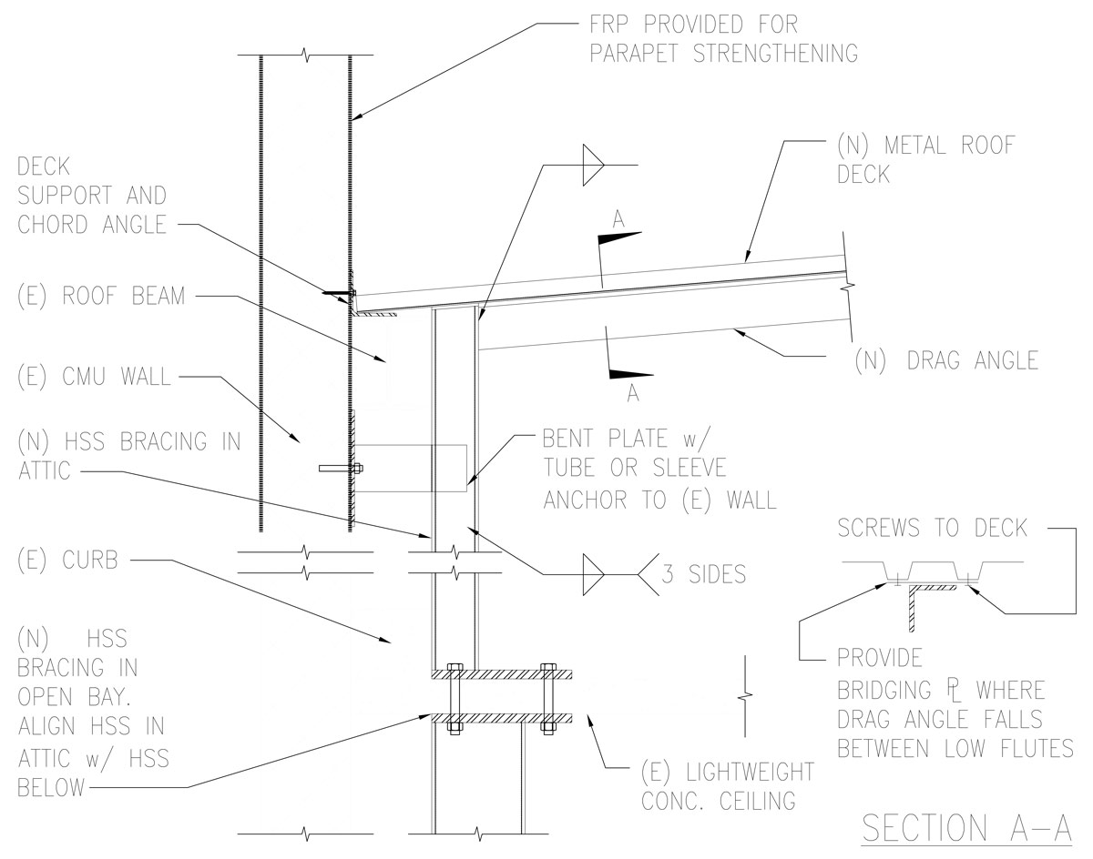
Figure 3. Bracing and deck connection detail.
One significant deficiency uncovered was the lack of a competent structural diaphragm at the roof. Neither existing horizontal rod bracing nor tongue and groove sheathing were found to have adequate strength and detailing for the diaphragm demands. In addition to not having sufficient shear capacity, the existing tongue and groove sheathing was in poor condition. Since the project also required removal and replacement of all roofing materials and insulation, the design-build team decided to replace the wood sheathing with metal roof deck. This substitution not only addressed structural concerns but served as a long-term betterment included within the project budget. Transfer of shear forces to the exterior masonry walls was accomplished using continuous steel angles, which also acted as chord reinforcement (Figure 3). Due to the significant length of the walls, the ungrouted and unreinforced masonry was found to be compliant for in-plane seismic forces.
Wall Strengthening
Although the exterior masonry walls were found adequate to resist in-plane shear forces, strengthening for resistance to out-of-plane forces was required. In addition to seismic forces, wind pressures based on a risk category II with a wind speed of 130 miles per hour were considered.
Previous conceptual planning studies recommended the use of fiber-reinforced polymer (FRP) strips to increase the capacity of all exterior walls. On the surface, this option appeared as the most efficient design solution. However, when considering constructability, existing conditions, and historical preservation, this option presented several major hurdles. To resist forces in both directions, FRP is required on both the interior and exterior wall faces. Application of FRP on the exterior surface involved several steps, including removal of existing stucco, preparation of the masonry surface, application of FRP, and then reapplication of stucco to match the remaining historic finish. Preliminary field assessments indicated the existing stucco was in good condition, meaning limited exterior finish work was needed if the stucco was not removed. Tests by the Contractor also found the existing stucco extremely difficult to remove, which increased estimated demolition costs and lengthened the schedule. Furthermore, matching new stucco with the existing historic stucco was a prime concern.
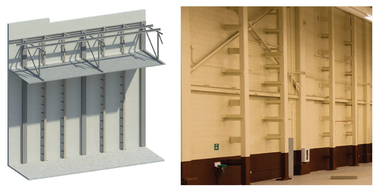
Figure 4. Steel wall bracing.
Because of these challenges, the design-build team developed an alternative structural steel bracing system that supports the walls only from the inside of the building (Figure 4). The bracing consists of steel HSS members spanning from floor slab to lightweight concrete ceiling and from ceiling to roof deck. The braces are attached to the masonry walls with steel angles welded to the HSS sections and a combination of tube screen and sleeve anchors connected to the ungrouted masonry walls. Either a wedge of solidified epoxy or an expanded metal sleeve bearing against the interior face shell of the masonry block provide anchor pullout capacity. The design-build team developed a field testing program to confirm the installed anchor’s pullout strength to alleviate any concerns about achieving adequate anchor capacity within the old masonry. This field testing program involved pull-testing anchors to a proof load of approximately twice the maximum capacity needed and holding the proof load for at least two minutes. Seven anchors were tested before construction began, and roughly one out of every 75 anchors were tested during construction.
This strengthening option, however, was not without its design challenges. Due to various renovations over the years, as-built drawings did not match actual field conditions. The Contractor performed a 3-D laser scan of the entire building and shared it with the design team to coordinate bracing locations and connections with existing obstructions. Particular attention to the connection detail at the roof was necessary to ensure unintended gravity loads are not imparted to the HSS sections. FRP was still utilized in limited locations not conducive to steel bracing. These locations included roof parapets and walls adjacent to the sliding hangar doors.
Despite the challenges, implementation of this bracing scheme proved a success. With the walls braced from the inside, the originally proposed FRP was largely eliminated and the historic exterior stucco was predominately retained. This reduction in construction effort saved over one million dollars, allowed the contractor to comfortably finish construction a month ahead of schedule, and greatly minimized impacts to the existing historic façade.
Blast Hardening
The exterior façade of the building (including masonry walls and hangar doors) was also analyzed for resistance to blast pressures in accordance with UFC 4-010-01, DoD Minimum Antiterrorism Standards for Buildings. As this historic building does not meet the Military’s current conventional construction parameters, dynamic blast analyses were performed on the ungrouted masonry using the United States Army Corps of Engineers’ Single-degree-of-freedom Blast Effects Design Spreadsheet (SBEDS). It was found that no additional strengthening of the masonry walls was required to meet the specified threat scenario.
In addition to the walls, three large, sliding hangar doors were analyzed and subsequently strengthened for blast loading. The doors were retrofitted with heavy steel plates to withstand blast overpressures and a tethering system to keep the doors from falling into the building if they were to shift off their rail supports during a catastrophic event. During the design of this tethering system, careful attention was paid to avoid adding considerable additional stress to the existing lightweight concrete ceiling. The contractor’s 3-D scanning and site surveys were invaluable tools in coordinating the load path for the tethering system.
Structural Repair
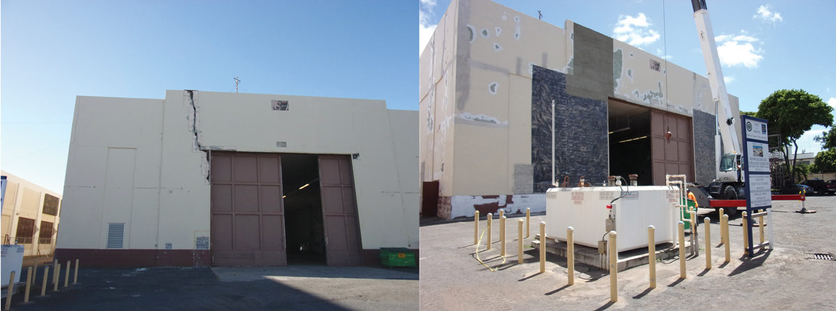
Figure 5. Extensive repair with FRP strips.
Deterioration of the existing structure also posed challenges at Building 26A. For example, several large cracks with significant displacement and slip were identified in the exterior masonry walls adjacent to one of the large hangar doors. To address this condition, the masonry cells adjacent to the crack were filled with expanding foam so that the masonry cells at the crack could be grouted without grout filling the entire wall. This ensured that the building’s seismic mass was not appreciably impacted. Also, FRP strips were added across the large cracks to provide continuity for transfer of forces from one side of the crack to the other (Figure 5).
Significant deterioration in the existing roof and corrosion of several steel members uncovered during demolition also posed considerable challenges. However, since the designers and builders were on the same team, these unforeseen conditions were quickly identified and efficiently addressed with sound, constructible solutions such as incorporating reinforcing plates or providing additional connection hardware that had minimal impact on the project budget and schedule.
The successful upgrade to Building 26A highlights the beneficial aspects of the design-build process, particularly when dealing with historic renovations. This collaborative approach between designers, constructors, and end users fostered creative solutions that resolved many difficult challenges and reduced overall risk in a holistic manner. Even with encountering numerous unforeseen conditions, Building 26A was renovated under budget and ahead of schedule.▪
Project Team
Owner: NAVFAC Pacific
Structural Engineer of Record: Baldridge & Associates Structural Engineering, Inc. (BASE)
Special Inspector of Record: BASE
CM/GC: Hensel Phelps
Architect of Record: Matsunaga & Associates, Inc.
Historical Architect: Mason Architects, Inc.
Structural Steel Erector: IG Steel
Hangar Door Subcontractor: GPS Specialty Doors