
Strange Bedfellows – The Liberty of the Seas® and an Abandoned Grain Elevator Foundation
The Port of Galveston has served as a hub for the cruise industry since the early 1990s and ranks as one of the busiest cruise ports in the U.S. Its facilities handle more than one million cruise passengers each year. When the industry demanded increased terminal capacity and throughput, the Port was quick to oblige. However, could consulting engineers with Horner & Wyatt in Kansas City, Missouri, who were responsible for the design of a grain elevator complex for the Galveston Wharf Company in 1930, have possibly envisioned their part in accommodating the Port’s expansion of Terminal 2?
For nearly seven decades, the grain elevator played a pivotal role in Galveston. Operations of the grain elevator commenced in 1931 and continued until 1998. Three “banks” of silos with a storage capacity of 5.2 million bushels enabled Galveston to be among the nation’s largest exporters of cotton, flour, sulfur, fertilizer, chemicals and grain while the Wharf Company operated. The 168 reinforced concrete silos, each 20 feet in diameter and over 100 feet tall, were supported on 40-inch thick reinforced concrete mat slabs and more than 12,000 thirty-foot long timber piles spaced at 30-inches on center, each way. Figure 1 illustrates an elevation view of one of the original grain elevators.
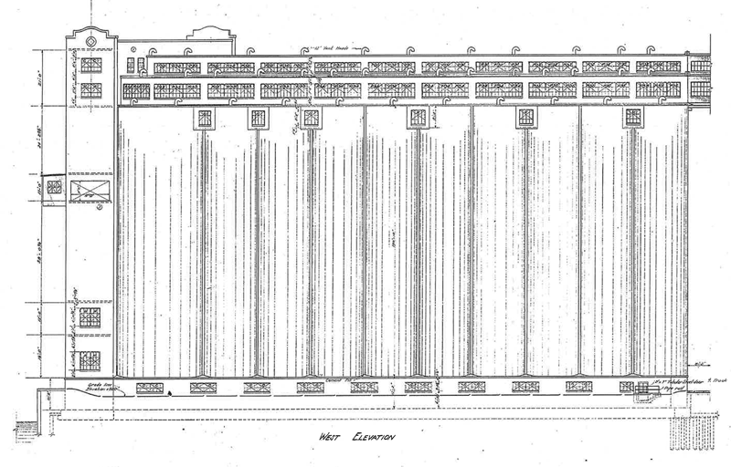
Figure 1. Elevation view of Grain Elevator Storage C. Courtesy of Horner & Wyatt.
In June 2003, the abandoned grain elevator site made way for the Port’s $30 million cruise terminal expansion plan with the demolition of the elevator, railcar unloading facilities and offices, and the implosion of the 236-foot tall “head house.” The mat slabs were abandoned in place.
In 2013, Royal Caribbean Cruises, Ltd., announced its desire to operate one of its Freedom-Class vessels, the MS Liberty of the Seas®, from the hub port at Galveston. The Liberty of the Seas has a length of 1,112 feet, a beam of 184 feet, a height of 209 feet above the waterline, a draft of 28 feet, an average crew size of 1,300, and fifteen passenger decks accommodating as many as 4,370 passengers.
The existing Cruise Terminal 1 and Cruise Terminal 2 facilities encompass approximately 90,000 square feet. To accommodate larger vessels and to process the ever-increasing number of passengers efficiently, the Port initiated plans to expand the Terminal 2 facility by approximately 60,000 square feet and solicited tenders from design-build teams in 2014.
Webber, LLC, a construction firm with headquarters in The Woodlands, Texas, was awarded the design-build contract in late 2014. They partnered with BEA Architects, Inc. (BEA) and Lockwood, Andrews & Newnam, Inc. (LAN), a planning, engineering and program management firm, to design the facility and to prepare the construction documents. Professional Service Industries, Inc. (PSI) was engaged to provide supplemental geotechnical engineering services. The $12.7 million project includes a two-story, 55,000 square foot main building that accommodates security screening, ticketing, and check-in, with seating accommodations for approximately 2,500 passengers. A two-story, 5,000-square-foot connector bridge accommodates the security-controlled passenger embarkation and disembarkation process.
The main building is comprised of a pre-engineered metal building (PEMB) with a full mezzanine framed using open web bar joists and wide-flange steel beams. The connector bridge is also a PEMB with a second level framed using wide-flange steel beams. The ground floor of the main building consists of a conventionally reinforced concrete slab supported on select fill. The ground floor of the connector bridge consists of precast concrete hollow core planks with a topping slab supported by cast-in-place concrete beams and plinths founded on shallow spread footings.
Project Challenges
The bridging documents prepared by AECOM, on behalf of the Port’s alternative delivery strategy, programmed the terminal expansion immediately adjacent to existing terminal buildings whose foundations consist of auger-cast piles. The team was aware of the existence of an abandoned grain silo foundation beneath the footprint of slightly more than half of the proposed expansion and was keen on taking advantage of it for support of some of the superstructure. The remaining area of the expansion was undeveloped.
The site is identified by the Federal Emergency Management Agency (FEMA) as a flood hazard area, and the current Flood Insurance Rate Map (FIRM) lists a Base Flood Elevation of 11.0 feet using the North American Vertical Datum of 1988. When the FIRM is updated in the near future, the base flood elevation will be increased to 12.0 feet. As such, the ground floor of the main building was established with a finished floor elevation of 13.0 feet to provide the necessary freeboard above a storm surge event, with a probability of occurrence of one percent each year. Existing grades across the proposed site varied between 5.2 feet and 7.8 feet. It was necessary to import five to eight feet of select fill contained by perimeter closure walls to enable a soil-supported ground floor slab. A storm surge event would impose hydrostatic, hydrodynamic, and wave loads, as prescribed by ASCE/SEI 7 and ASCE/SEI 24, on the perimeter closure walls.
When detailed design commenced, geotechnical engineering analyses, including laboratory testing for consolidation of a weak soil stratum located between 8 and 25 feet below existing grade, were not yet complete. When consolidation testing was completed, the structural
engineering team was presented with the potential for significant settlements given the magnitude of the anticipated surcharge loads from the superstructure and the overburden from the imported fill.
The overburden would impose down drag effects on both new and existing piles, significantly reducing the capacity of the piles to resist compressive loads. Moreover, the potential for significant differential settlement across the proposed new building footprint required design solutions to ensure compliance with the Americans with Disabilities Act and Texas Accessibility Standards.
As with any expansion or renovation project, design teams are always challenged with maintaining the form, function, aesthetics, structural integrity, and life safety systems of the existing facility. This project was no exception. Also, the construction team had to accommodate on-going operations at the existing cruise terminals, which created numerous logistical challenges.
The Port had only a limited budget to facilitate expansion and renovation of Cruise Terminal 2. Webber tendered a firm, fixed price offer to execute the program.
Collaborative and Innovative Solutions
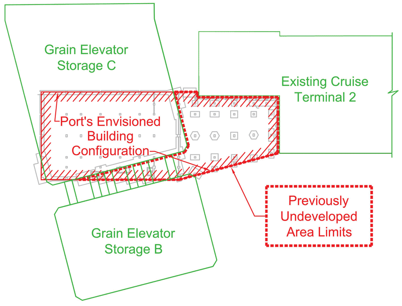
Figure 2. Plan view of the Port’s Envisioned Building Configuration. Courtesy of LAN.
The design team developed a number of solutions to accommodate the Port’s envisioned building configuration. Figure 2 outlines the original foundation design that accommodated the existing conditions and the compressible subsoil stratum, and prevented adverse down drag effects on existing pile foundations. Supplemental auger-cast pile-supported mats were incorporated to accommodate portions of the main building that fell beyond the footprint of the existing silo mats. A structural slab supported by auger-cast piles and pile caps was utilized for a previously undeveloped portion of the site. Moreover, minimum pile-setback distances were maintained along the interface with the existing facilities to mitigate otherwise adverse vibration transmission during pile driving operations.
The team collaborated to ensure that the existing grain silo mat foundation, located 13 feet below finished floor, had the capacity and integrity to accommodate 1,500 psf of soil overburden and the anticipated dead, live, and environmental loads imposed on the superstructure. The assessment engaged the geotechnical and structural engineers and Webber’s technical design services and construction teams.
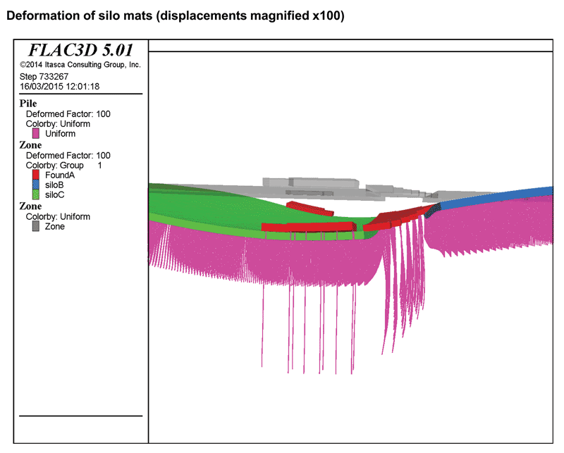
Figure 3. FLAC3D modeling – mat deformations. Courtesy of Webber.
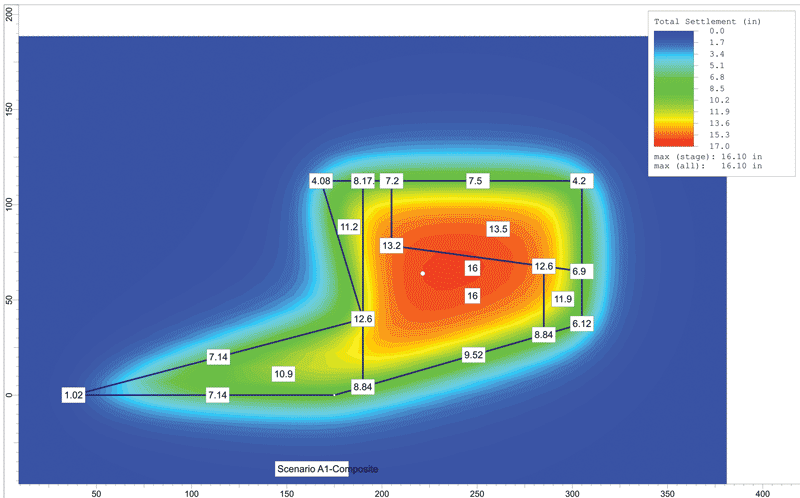
Figure 4. Settle3D modeling – Undeveloped Area Settlements. Courtesy of PSI.
Uniform and differential settlements were estimated using sophisticated three-dimensional modeling software (FLAC3D and Settle3D; refer to Figure 3 (page 22) and Figure 4). An analysis of the load-carrying capacity of the existing grain silo mat foundation was performed based on a review of the grain elevator design drawings. A non-destructive testing program was initiated to substantiate the integrity of the existing reinforced concrete mat foundation and timber piles. The program included a visual inspection of the exposed mat slab (Figure 5) and measurement of its surface hardness and penetration resistance. Rebound hammer test results were correlated with concrete core sample testing. A timber pile was exposed and visually inspected for signs of deterioration or distress. The results of the assessment were positive, and design documents were finalized for construction. Unfortunately, accommodating the unanticipated site subsoil conditions was cost-prohibitive.
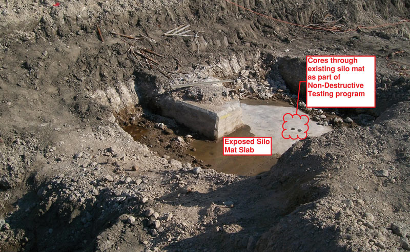
Figure 5. Existing silo mat foundation. Courtesy of LAN.
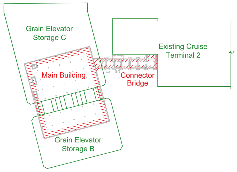
Figure 6. Plan view of the revised building configuration.
With the Port’s cooperation, BEA initiated a complete reconfiguration of the terminal expansion. With the exception of the connector bridge, the entire main building was positioned above two of the existing grain silo mat foundations, as illustrated in Figure 6. The team was determined to utilize a grade-supported ground floor slab for the entire main building. However, the pair of silo mat foundations are separated by 30 feet, and the potential for subsoil consolidation between the pair of mat foundations had to be mitigated.
PSI prepared a narrative for pre-loading that area of the site with a soil embankment 20 feet high. PSI further recommended the installation of vertical wick drains to accelerate the consolidation effort. The construction team implemented this action plan a few months before construction commenced in the affected area.
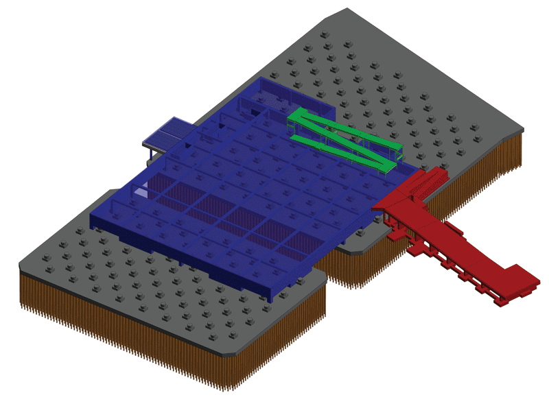
Figure 7. BIM rendering – foundation and ground floor systems. Courtesy of LAN.
The connector bridge was designed with a structural ground floor slab to preclude the need for any imported select fill. Furthermore, shallow spread footings were sized with an allowable bearing capacity of only 1,500 psf. An expansion joint was introduced between the connector bridge and the main building to accommodate differential movements.
Refer to Figure 7 for a BIM rendering of the final structural solution for the foundation and ground floor systems.
Project Benefits/Successes
Webber and its subcontractors executed the seven-month long construction program with no cruise line disruptions, security breaches, or safety “recordables.” The expanded and renovated facility has been operational since July 2016.
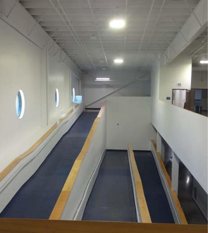
Figure 8. Disembarking passengers ramp. Courtesy of Webber.
The United States Customs and Border Protection is one of the Department of Homeland Security’s largest and most complex components. The required segregation of disembarking and embarking cruise passengers can often substantially increase passenger “cycle” times. BEA successfully incorporated an interior ramp (Figure 8), coupled with elevators and escalators, that resulted in a significant improvement in passenger throughput. Passengers can navigate from curbside to the ship’s gangway within nine minutes.
Most importantly, the Webber team was able to deliver the project within the Port’s approved budget. The Port, Royal Caribbean (et. al) and cruise passengers can enjoy the benefits of a well-conceived and executed expansion initiative for years to come. Furthermore, BEA maintains that subsequent site expansion efforts are viable and can ultimately accommodate even larger passenger vessels. Royal Caribbean’s MS Harmony of the Seas®, with accommodations for up to 6,360 passengers, was launched on June 19, 2015, and is currently deployed to Port Everglades.
There is no doubt that the abandoned grain elevator foundations can accommodate any future expansion. Could Messrs. Horne and Wyatt have envisioned such a legacy?
Conclusion
Despite the many challenges, the success of the Cruise Terminal 2 expansion project was made possible because the Port of Galveston, Webber, BEA, LAN, and PSI collaborated on solutions that incorporated imagination, technology, and innovation. With collective diligence and persistence, the team delivered a benchmark for efficiency. When you next embark on a cruise via the hub port at Galveston, know that you are standing above robust foundations designed by
engineers in the 1930s.
Project Team
Owner: Port of Galveston, Galveston, TX
Structural Engineer: Lockwood, Andrews & Newnam, Inc. (LAN), Houston, TX
General Contractor (Design-Builder): Webber, LLC, The Woodlands, TX
Design Manager: Webber, LLC, Technical Services, The Woodlands, TX
Architect: BEA Architects, Inc., Miami, FL
Geotechnical Engineer: Professional Service Industries, Inc., Houston, TX
MEP and Civil Engineers: LAN, Houston, TX