
Extending New York City Subway lines requires deep excavations in a congested urban environment while protecting adjacent facilities. The 100-foot-deep Metropolitan Transportation Authority (MTA) No. 7 Line Station excavation, through soil and rock between West 34th and 35th Streets, was no exception.
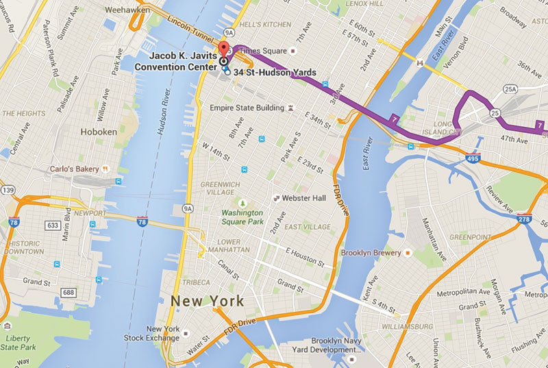
Figure 1. Location plan with No. 7 Line in view.
MTA 7 Line Extension
A 1.5-mile extension of the No. 7 Flushing Subway Line in the Borough of Manhattan, New York City, from its previous terminus at Times Square, was recently constructed. The project was constructed for the MTA and extended south and west to a new 34th Street, Hudson Yards Station (Figure 1). This improvement grants more accessibility to the area, including the Hudson Yards Redevelopment Project and the Jacob K. Javits Convention Center. Future plans will consider tunnel extensions west under the Hudson River to New Jersey.
The excavation of a West 34th Street cavern marked the start of construction in December 2007. The construction of the tunnels began in June 2008 with the use of tunnel boring machines. The No. 7 Line extension was opened to the public on September 13, 2015.
Elevations provided in this article are relative to New York City Transit Authority Datum at 97.347 feet below USGS mean sea level (NGVD 1929).
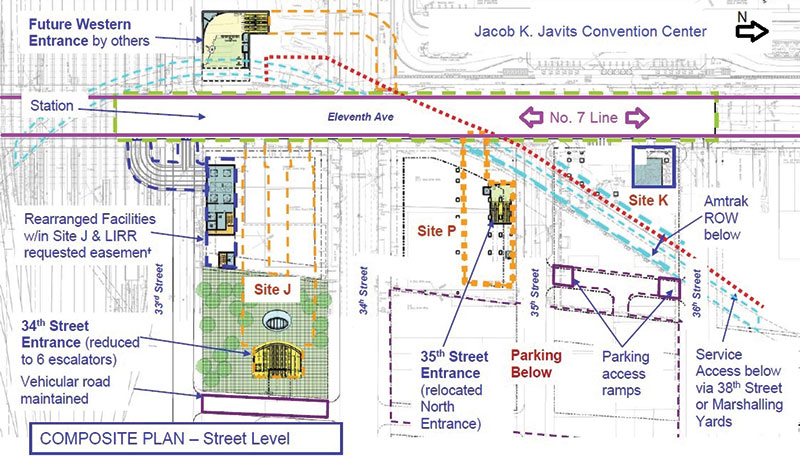
Figure 2. Composite plan showing the No. 7 Line and Site P.
Excavation for the 35th Street Access
The Hudson Yards Station (Figure 2) consists of three floors: an upper mezzanine, lower mezzanine, and a platform level, with the platform level situated 125 feet below street level. Access is provided from 34th Street with secondary access at 35th Street.
The focus of this article is the “Site P” portion of the 34th Street Station which provides the secondary access from 35th Street. Site P is located across from the Jacob Javits Center between 34th and 35th Streets and 10th and 11th Avenues. The Site P design and construction required soil and rock excavation to depths of over 100 feet into the rock adjacent to an Amtrak right of way (ROW) below.
The unique aspects of the support of excavation (SOE) work included requirements for phased excavation to tie into other 7 Line contract work in the extremely congested urban area. This involved concurrent de-tensioning of existing tie-back systems supporting site access to the Amtrak tunnel.
Contractor John P. Picone (JPP) was awarded construction of the Site P Station Entrance for the station in September 2012. JPP performed the excavation for the facility in two phases, Phase I and Phase II (Figure 3). Phase I consisted of a temporary SOE system for both soil and rock for the upper mezzanine station entrance. Phase II was more complex as it required the installation of another temporary SOE for the excavation of soil and support of vertical rock faces for the descent into the ground to connect with an existing “Shaft P.”
Shaft P had been previously excavated to connect the Phase I & II excavations to the 34th Street Cavern and No. 7 Line tunnels, while also providing access to the cavern area during its construction.
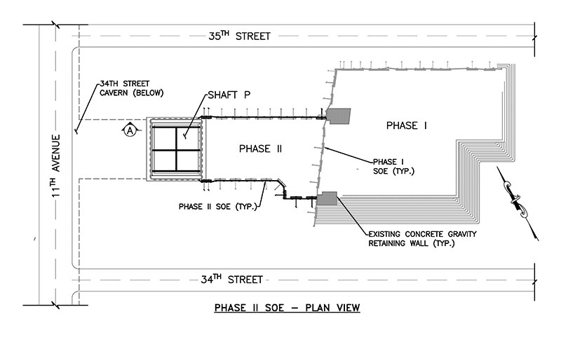
Figure 3. Plan view.
The ground-surface, street-level elevation is at approximately 128 to 130 feet (Figure 4). Phase II required excavation to depths ranging from approximately 40 to 95 feet below the ground surface to connect to the existing Shaft P. The rock was excavated on a slope to facilitate escalator access construction from track level to ground surface. The temporary SOE supported up to 35 feet of soil overburden down to the top of bedrock between the existing Phase 1 and Shaft P sites.
Soil and Bedrock Conditions
Geotechnical data reports were prepared for the site by MTA geotechnical consultants in advance of construction. Borings found about 10 to 35 feet of overburden soils consisting largely of urban fill over glacial till/decomposed rock before encountering the bedrock surface. The reports indicated massive granite (granodiorite, diorite, granite) and schist (mica schist, biotite-hornblende schist, gneissic schist) rock groups constituting the majority of the rock. Discontinuities in the rock, including fractures and multiple joint sets, were found in both rock groups. Joints are fractures in the rock mass where there has been little or no movement, and a joint set is a group of joints of similar parallel orientation in space. The strike and dip orientation of the rock discontinuities were also measured during excavation.
Groundwater was found during design phase borings at about elevation +101 feet.
Challenges
The phased construction presented several design challenges. The existing SOE wall between Phase I and Phase II had to be integrated into the new Phase II SOE, and the existing western SOE wall at Shaft P had to be partially removed to build the SOE necessary for the excavation. The installation of the north and south walls of the Phase II SOE also had to be tied into both the existing Shaft P and Phase I SOE.
As excavation proceeded through the upper soils, SOE soldier piles driven through the soil to the top of rock were exposed. As the rock was excavated and exposed below the pile tips, additional rock support and pile toe pins were added at some locations to maintain pile bearing during excavation. Pile toe pins consisted of #14 reinforcing bars grouted into 5-foot deep by 2½-inch diameter rock sockets.
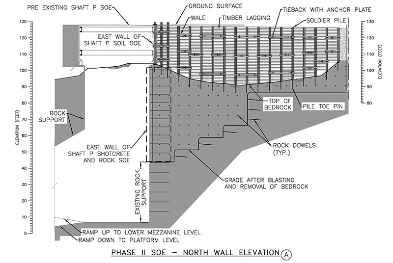
Figure 4. Elevation view of the Phase II SOE.
Construction Solutions
Excavation was completed primarily with the use of excavators through soil overburden and then switched to controlled blasting and line drilling when rock was encountered. Blasting operations were controlled to limit vibrations below specified maximums.
The Phase II SOE (Figures 5 and 6) consisted of tied-back soldier piles and lagging. The depth was based on the depth to rock, ranging from approximately 18 to 37 feet. Soldier piles were driven to the top of rock with toe-pins installed at the pile tips for toe restraint as excavation progressed. Tie-backs were preloaded strand anchors drilled and grouted into bedrock. Wales were seated on diagonally cut HP pile sections that were welded to the soldier piles to anchor the exposed end of the tieback.
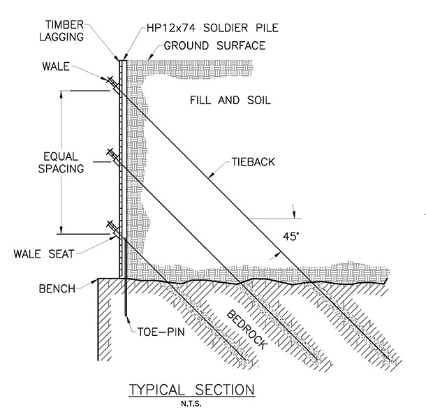
Figure 5. A typical section of the SOE.
Figure 6. A view of the Northwest corner (towards the Javits Center) of the Phase II Soil SOE.
Two gravity retaining wall structures were constructed to support portions of the Phase I SOE while providing a means for removal of a portion of the existing west wall of the Phase I SOE and commencement of the Phase II SOE.
Rock bolts and shotcrete bracing the eastern Shaft P rock wall were removed. The SOE between the Phase II excavation and Shaft P was partially demolished to allow connection of the north and south walls of the Phase II and Shaft P SOE’s, and the ultimate connection to the tunnel (Figure 7).
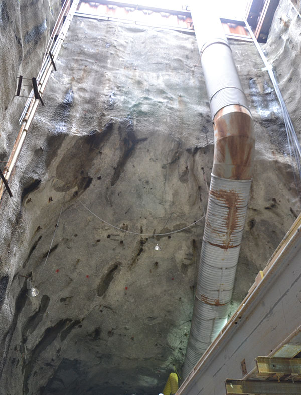
Figure 7. A view from the bottom of Shaft P (looking west) showing the tunnel access.
Rock support design required field mapping of the rock structure and the joint sets. Field mapping results were compared and coupled with the design-phase rock core information provided by the MTA. The data was used in rock mechanics analyses for final design and layout of the rock bolting construction. The design also incorporated the sequencing requirements for the removal of rock with the installation of reinforcement at the exposed rock faces. Eight-foot, minimum-depth rock dowels and mesh were installed into the rock in a typical six-foot by six-foot pattern. Typical rock bolts and mesh installed below the SOE are shown in Figure 8.
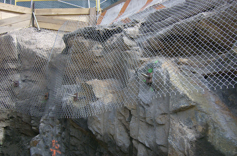
Figure 8. Typical rock bolts and mesh below the SOE.
Conclusions
The shallow bedrock and phased construction required a real-time-design approach to address excavation techniques, support of rock faces, and integration of existing SOE’s. This method involved assessment of actual soil and bedrock conditions including field mapping of rock structure as the excavation progressed to expose actual conditions. Field data was analyzed for the final design of rock bolting to stabilize the faces of the deep bedrock cut, protect adjacent construction, and permit construction of the subway station in a heavily congested urban location.▪