
Non-destructive Testing (NDT) plays a critical role in the understanding of existing structures. Investigative techniques available offer practical, efficient, and cost-effective solutions to obtaining information on quality, construction, and performance that may be otherwise hidden to the naked eye. The use of NDT tools vastly reduces the need for exposing embedded structure through probing, and assists in making more informed decisions when samples or probes must be performed.
Technology and products develop rapidly in many industries. The Information Technology (IT) and Automotive industries are good examples of this phenomenon, where high global demand drives the availability of funds for research and development. As a result, advancements in products and new technology are quick to emerge. The development of NDT test equipment, however, has not been so rapid to develop since its introduction. In 1950, The Schmidt Hammer, also known as “Swiss Hammer,” became the world’s first patented non-destructive testing method for concrete. The use of Ground Penetrating Radar (GPR) (Figure 1) did not gather much momentum as a mainstream inspection technique until the 1980s and 90s.
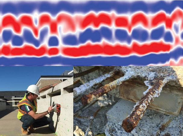
Figure 1. Modern GPR equipment, raw data, and corroding steel reinforcement. Courtesy of Echem Consultants LLC.
Contrary to the IT and Automotive industries, the demand for concrete inspection products and associated technology has typically been restricted to a limited number of professionals and inspection firms with a foothold in the field of NDT. Firms seeing a limited global demand for these products did not allocate significant budgets for equipment purchase, and allocated even less budget for employing specialist investigators to collect and analyze data. This left the NDT world waiting extended periods for new generations of equipment to develop.
Over the last ten years, significant advancements have been made in the development of NDT technology that now allow for detailed and accurate inspection of concrete. There are numerous pieces of equipment and test methods which allow for an extensive understanding of a structure with limited material removal.
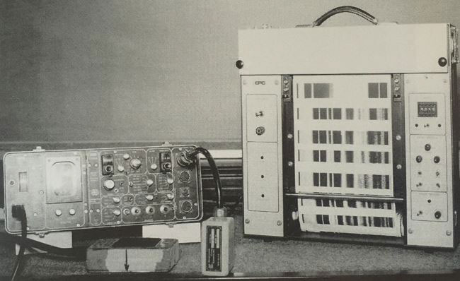
Figure 2. SIR8 GSSI GPR equipment – approximate year 1999. Courtesy of GSSI and Echem Consultants LLC.
Despite the rapid advances that have occurred over the past 10 years, this article explores some of the significant advances that have happened in the last 20 years in the development of GPR equipment for its use in NDT inspection of concrete. It briefly discusses how the GPR technology works, what improvements have been made to the units and what the most current equipment is now capable of achieving. Figures 2, 3 and 4 show how far GPR equipment has come in the last two decades.
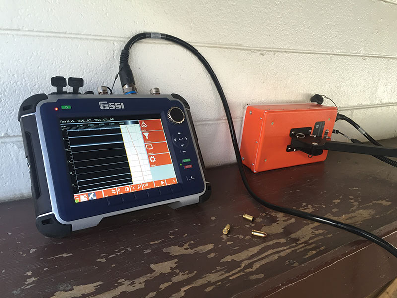
Figure 3. SIR4000 GSSI GPR equipment – 2016. Courtesy of GSSI and Echem Consultants LLC.
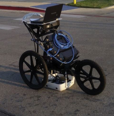
Figure 4. Bridge Inspection Unit with single antennae. Courtesy of GSSI and Echem Consultants LLC.
NDT of Concrete Structures
By the late 1980s and early 1990s, the only technique capable of scanning through concrete and providing imaging data suitable for determining the structure’s arrangement was Ground Penetrating Radar (GPR). Ideally, this method was combined with rudimentary metal detectors. Even the combined use of these two techniques was somewhat unreliable regarding their functional operation and the quality of data output.
One positive factor during this time was that only a few firms provided these services. The reduced number of companies meant that operators and data analysts were typically well trained, with practical experience. However, since the equipment was still quite unreliable, even unpredictable, and the data was of poor resolution, interpretation mistakes were inevitable. This did some damage to the industry as a whole, often creating a feeling of skepticism about the technology and also about those who purported to be experts in their field.
This meant that traditional methods of inspection, such as probing, were heavily relied upon, for a significant period, to answer questions about the arrangement and condition of concrete (mass & reinforced).
In the past 20 years, GPR equipment has advanced from being unreliable and malodorous (due to significant carbon dust ejections in early equipment) to one which is now more reliable and accurate.
Ground Penetrating Radar
What is it?
Ground Penetrating Radar (GPR) is an imaging technique that uses wide-band sinusoidal electromagnetic waves to produce high-resolution images of the subsurface materials, typically from zero to approximately 33 feet (10 meters) in depth. GPR is an effective tool for subsurface inspection and quality control on engineering construction projects. The survey method is rapid, nondestructive and noninvasive. (Yelf, R.)
What can it provide?
When combined with the use of other methods of inspection, such as magnetics and acoustics, GPR remains the most commonly used and reliable technique to assess a concrete structure. Interpretation of GPR data commonly helps to confirm the following main questions asked of a concrete structure:
- Concrete component thickness and reinforcement cover thickness (including variations from the original design)
- Existence, spacing, arrangement, and depth to embedded reinforcement
- Existence of other features such as pre-stressing cables, embedded conduits, and pipes
Condition information can also be recovered using GPR, including the determination of:
- Existence, location, and severity of voiding and honeycombing within the concrete
- Existence and location of delamination /separation parallel to the concrete surface
- Relative moisture content (laboratory testing still required for accurate measurement)
It is important to remember that condition information is most accurately achieved when combined with other inspection techniques such as half-cell potential, linear polarization resistance (LPR), moisture meters, infrared thermography, and ultrasonics. No one technique can provide all the answers, especially if the problem is reinforcement corrosion. (Watt, David S.)
How does GPR work?
An electromagnetic pulse of energy is sent into the structure under investigation. When the pulse passes from one material type to another, the pulse wave velocity changes. This shift in wave velocity at the boundary between material types causes energy to be reflected back to the receiver and provides a record of the interface.
Both the transmitted and received signals are waves. The system utilizes the principle that radio waves travel at different velocities through different materials. Since the velocity is dependent upon the electrical characteristics of that material, the change in that electrical difference can be recorded by the impulse radar. (Daniels, D. J.)
Data Interpretation
Radar data, in its analog form, is comprised of a series of sinusoidal lines that require skillful interpretation to provide meaningful results.
The simplest items to understand in a typical section of data scan are metallic inclusions such as reinforcement bars, dowels, pipes, and pre-stressing tendons. Their successful identification, however, can still require an experienced eye, as data response and data resolution can change dramatically from material to material so that a drilled hole or a piece of aggregate high, in iron for example, could be mistaken for a metal inclusion. Experience with and knowledge of the equipment is crucial to successful data interpretation.
Data Resolution
On a positive note, data resolution has improved significantly over the past 20 years. Radar data in the 1990s was burnt onto thermal paper using electrically driven belts; as a result, the printers threw out carbon dust and the data was often smudged and of poor quality. Today, radar data is much cleaner and clearer and is digitally recorded for computer use. A comparison of data resolution is shown in Figure 5.
To generate three-dimensional (3D) maps with traditional antennae heads, the surface of the concrete requires multiple passes on a grid pattern in both X and Y coordinates. There are bridge inspection units on three wheel carts that make data collection for smaller bridge decks faster; however, the time required for multiple passes and subsequent data processing makes the process somewhat time-consuming.
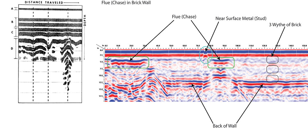
Figure 5. Left: Early GPR data; approximate year 1987. Right: GPR data; approximate year 2015. Courtesy of ACSESS Digital Library and Echem Consultants LLC.
Modern Mapping of Conditions
One of the most recently developed pieces of GPR equipment emerging in today’s market is the multi-array (fitted with multiple antennae) bridge inspection unit (BIU). Although typically linked to bridge inspections, this device can map the arrangement and condition of any horizontal structure, providing specific information on reinforcement cover depth, delamination, voiding, and relative moisture content. Its use does not have to be limited to concrete either. The technology allows for scanning through asphalt and other masonry types, such as brick and stone pavers; however, it was specifically developed with structural health assessments in mind.
This system is comprised of multiple antenna frequencies, instead of using the traditional individually mounted antenna set up, for data collection. The antenna array can provide a highly detailed 3D underground tomography of the mapped surface. This greater detail enables a more accurate diagnosis of a structure’s thickness, reinforcement placement, retained moisture, and levels of deterioration, most commonly associated with moisture or delaminations. As with all NDT techniques, the use of this equipment must be combined with additional investigation techniques to corroborate the data and verify the results.
The design of the system allows for rapid, accurate, high-resolution data to be collected at speeds of up to 12 miles per hour. When comparing this data to vehicle-mounted air-coupled (not in contact with the surface) GPR arrays, which gather data at higher speeds, the resolution is far more defined. This is due to intimate contact with the surface and a high density of data (Figure 6).
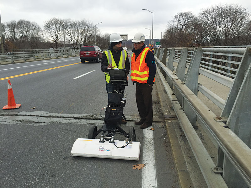
Figure 6. Multi-array Bridge Inspection Unit in operation scanning bridge deck arrangement and condition. Courtesy of Echem Consultants LLC.
Data is collected in plan and section up to two feet in depth. Typical data presentation is stitched together to provide maps of the areas tested and associated conditions. The integrated software correlates propagation velocity and attenuation to areas of risk. Maps of concrete cover and moisture are generated (Figure 7). Section details can be extracted from any data point on the plan; therefore, where the moisture or degradation is highlighted, the section can be reviewed for visual affirmation of the condition. This high level of detailed data allows the team to go back to areas of risk and confirm their condition. This makes interpretation and decision making for repair strategies much easier for projects involving bridges, roads, parking garages, tunnels, warehouses, and many other concrete slab applications.
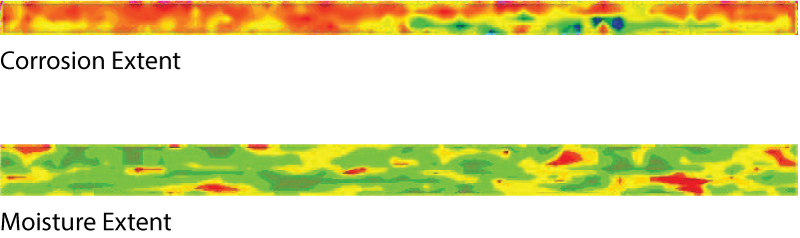
Figure 7. Multi-array Bridge Inspection Unit contour plot data presentation. Courtesy of ACSESS Digital Library and Echem Consultants LLC.
Summary
The use of non-destructive testing equipment and its development for the assessment of concrete structures has gathered positive momentum over the past two decades. The benefits of using the technology have been embraced by a great many in the construction industry. It is now much better understood and is relied upon by owners and project teams to understand their structures better, while vastly reducing the need to damage them through exposure or probing.
GPR bar mapping devices have now become so reliable and user-friendly that they are no longer only exclusively used by NDT companies. Mobile GPR units are used to map bar positions, and can do so accurately.
Bridge deck inspection units are rapidly changing, and improving, at a time when the United States’ infrastructure rating is at its lowest. The need to understand critical conditions from the scanned surface, in a non-destructive manner, is becoming ever more vital. It is now feasible to achieve complex data mapping with available GPR technology. This includes additional reinforcement layers, complex construction arrangements, increased moisture content, evidence of voids, or reinforcement corrosion conditions.
The speed of response, the detailed data collection, and the advances in software are leading to a better understanding of existing conditions. As the technology continues to be enhanced, the resulting data from surveys and studies are being correlated with other NDT methods. This helps to define patterns in deterioration and associated GPR responses. Programs created by the Federal Highway Administration (FHWA), such as the Strategic Highway Research Program 2 (SHRP2), are highlighting the best methods for rapid collection. It is presumed that these technologies will continue to develop and become even more accurate in the future.▪
References
Daniels, D.J. Ground Penetrating Radar, Institution of Electrical Engineers 2004
Guidance on Radar Testing of Concrete Structures, Concrete Society Technical Report TR48 1997, The Concrete Society, Slough, UK
Yelf, Richard. Application of Ground Penetrating Radar to Civil and Geotechnical Engineering, (Published in 2006 by the Society of Exploration Geophysicists Japan and the Australian Society of Exploration Geophysicists).
Watt, David S. Concrete Building Pathology, edited by Susan MacDonald, (First published in 2003 by Blackwell Science Ltd)
IDS – Specialists in Multi-Channel Ground Penetrating systems
Non-Destructive Testing to Identify Concrete Bridge Deck Deterioration, SHRP 2 Report S2-R06A-RR-1
Kilic, Gokhan. GPR Raw-Data Order Statistic Filtering and Split-Spectrum Processing to Detect Moisture (Published May 2014 by the Department of Civil Engineering, Izmir University of Economics)