
Decades in conception and planning, the new Sanctuary for Sufism Reoriented in Walnut Creek, California, aims for a design life of centuries. The Sanctuary consists of a series of one-story domes above grade and a basement below (Figure 1). The largest dome is 78 feet in diameter and covers the column-free Prayer Hall, and smaller domes cover a variety of other spaces around the perimeter. A striking 38-foot tall base-isolated bronze sculpture reaches up from the basement to the oculus of one of the medium domes.
In an effort to fit into the surrounding residential neighborhood, the above-grade structure is much smaller than the basement (Figure 1). The below-grade level features a sky lit rotunda, a gallery, offices and a recording studio.
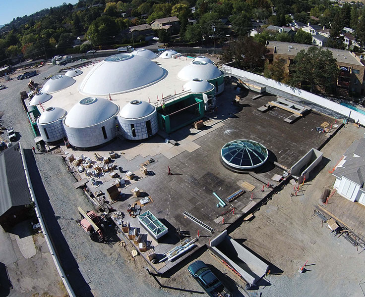
Figure 1. Aerial photograph during construction. Courtesy Sufism Reoriented.
The building will serve as the principal center of worship for Sufism Reoriented, a religious group with congregations in the San Francisco Bay Area and Washington, D.C. The congregation collaborated with Philip Johnson/Alan Ritchie Architects and Thornton Tomasetti as structural engineer, and hired Soga + Associates as the architect of record.
Elongated Design Life
Cast-in-place concrete was selected for the building, a choice influenced by the owner’s desire for an elongated design life with minimal maintenance. Other materials such as structural steel, precast concrete and concrete masonry were judged to be less durable for a variety of reasons, and therefore unsuitable. The smallest domes stand as the exceptions and consist of precast glass-fiber reinforced concrete.
When the owner initially expressed a desire for a design life in the range of hundreds of years, the structural designers recommended the use of performance-based design concepts because of the high seismicity of the site. Sufism Reoriented decided not to pursue this design option, but they did maintain their desire for a more robust approach than minimum code compliance. They understood that, although the code aims at life safety for occupants, significant damage to the structure may occur during a major seismic event. As a result, the building was designed using an R-factor of 1.25, the lowest response modification coefficient in the California Building Code (CBC), rather than the R-factor of 5 for special reinforced concrete bearing walls. This approach reduces the ductility demands on the structure and aims to keep seismic forces largely in the elastic range of reinforced concrete.
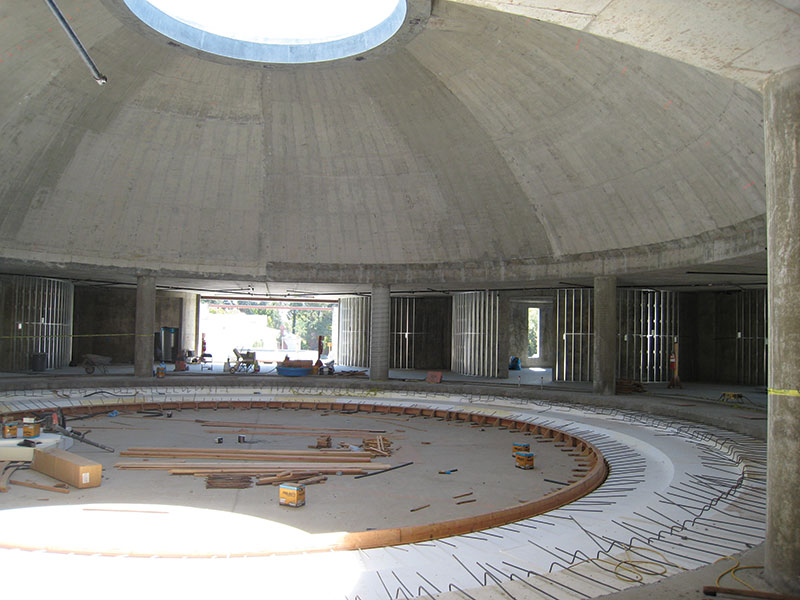
Figure 2. Main dome over Prayer Hall during construction.
Seismic Design of Shear Walls and Domes
Special reinforced concrete shear walls that are circular in plan serve as the lateral system for the above-grade portion of the Sanctuary. The twelve “drum walls” occur below the four 38-foot diameter medium domes and the eight small domes. The main dome sits on columns, as shown in Figure 2, and is stabilized by a concrete flat slab diaphragm at roof level that transfers the seismic forces to the drum walls.
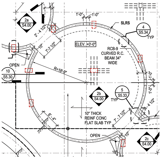
Figure 3. Partial plan of drum wall on columns below.
Because the basement has a rectilinear geometry, the drum walls typically sit on columns below (Figure 3). In addition to serving as shear walls, the 12-foot high drum walls act as beams spanning between the basement columns. The drum walls supported on columns were treated as discontinuous lateral system elements for design, and seismic forces acting on the columns were designed for the CBC’s over-strength load combinations. The ground floor slab serves as a diaphragm to redistribute shears from the drum walls to the perimeter retaining walls, which serve as shear walls.
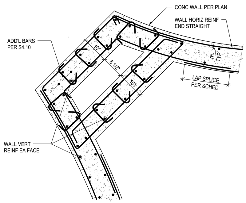
Figure 4. Boundary zone at drum wall.
Boundary zones were detailed within the drum walls where the stress criterion in ACI 318-08 Section 21.9.6.3 was exceeded, and typically these elements occurred where drum walls sit on columns. Because of the way the drum walls intersected in plan, some of the boundary elements have unusual configurations (Figure 4). Additional vertical dowels were added to anchor the drum walls into the supporting columns for uplift loads.
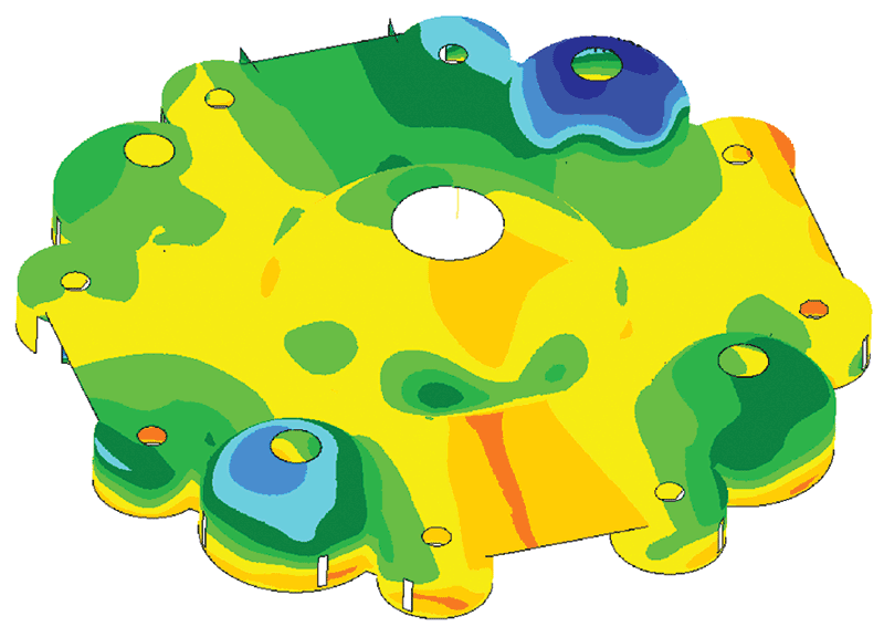
Figure 5. Finite element model of domes and drum walls.
A dome is such a stable structural form that an extremely thin shell is possible but, out of consideration for very long term durability, two mats of reinforcing were used with a minimum thickness of 7½ inches. The architects set the relatively shallow partial-sphere geometry of the domes initially, and it was confirmed by structural analysis. The domes and drum walls were modeled by finite element analysis with special attention paid to the intersections between the domes and the flat slab at the roof (Figure 5). The Morley Clark Nielsen method was used to calculate reinforcement for the domes from finite element results. Monolithic ring beams occurred at the top and bottom of each dome in order to carry the compressive and tensile hoop stresses respectively.
Small reinforcing bars were detailed in the domes, and in their top and bottom ring beams, in order to facilitate bending them to a curve. Similar reinforcing bar sizes were specified for the curved bars in the drum walls. In addition, the clear cover specified was one-half inch larger than that required in ACI 318 in order to give the contractor more tolerance for rebar erection.
Formwork for the domes consisted of closely spaced radial ribs of dimensional lumber, cut to curve and spliced. Thin plywood forms cut in wedge shapes were bent to curve and fastened to the ribs. The ribs were propped by conventional shores, which were braced at regular intervals for lateral stability. The concrete ring beams at top and bottom were placed first in order to insure that they, rather than the formwork, bore hoop stresses resulting from the wet concrete of the dome. The contractor shotcreted the domes in alternating pie-slice segments in order to minimize cracking from circumferential shrinkage.
Domes constructed with inflated formwork were considered by the owner, but the only version that held promise for economy included an integral roofing system that was considered to lack the desired long term durability.
The smallest domes are ¾-inch thick glass-fiber reinforced concrete with ribs. They are exposed to the elements, so thermal issues required consideration. The other domes, on the other hand, are covered by roofing and insulation and are more massive, which prevents large temperature swings. Oversized bolt holes with Teflon shims at the base connections of the GFRC domes insured that the thin shells could expand and contract from temperature swings without being overstressed.
Buoyancy
A recommended water table 10 feet below grade and a basement roughly 20 feet below grade, coupled with a single story above grade or none at all, made hydrostatic uplift a significant issue.
A concrete mat foundation was chosen because of its mass and the flexibility it afforded for future column placements during renovations. Additional ballast came in the form of a green roof over the ground floor slab outside the footprint of the above-grade story (approximately 250 pounds per square foot) and an eighteen-inch layer of gravel with a finish slab on top of the mat. Utilities such as plumbing lines were placed in the layer of gravel, which allowed for relatively easy future access. Near heavily loaded columns, the mat was thickened by placing pads on top of the mat within the gravel layer, which minimized excavation.
Concrete for the mat slab was required to reach a 4000 psi compressive strength at 56 days. The longer than usual time period for the achievement of design compressive strength allowed for the use of less portland cement, just 282 pounds per cubic yard, and an equal proportion of Class F fly ash to create a more environmentally friendly mixture.
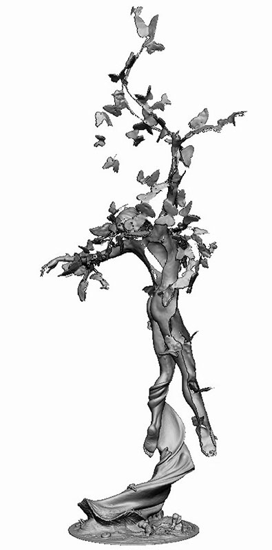
Figure 6. New Man sculpture. Courtesy Sufism Reoriented.
Sculpture
One of the highlights of the sanctuary is a 38-foot high bronze sculpture designed by a member of the congregation. The cloth-textured base of the sculpture supports the body, from which branches with butterflies rise to the full height (Figure 6). The body has numerous long holes cut in the surface, some as long as 15 feet. The highest butterflies are acrylic, the only portion of the sculpture that is not bronze.
As with the building structure, the owner desired a long design life for the sculpture. Using the CBC provisions resulted in bronze thicknesses of one inch. However, the fabricator stated it was not feasible to cast a structure that thick.
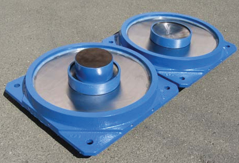
Figure 7. Interior of triple friction pendulum isolator.
To reduce seismic forces and therefore the bronze thicknesses, Thornton Tomasetti suggested base-isolating the sculpture. Base-isolating the sculpture significantly lengthens the dynamic period of the sculpture and reduces the seismic forces. Friction pendulum isolators were selected because they use durable materials such as stainless steel and graphite, and are understood to return to equilibrium after a seismic event (i.e. self-centering). The isolator supplier recommended four triple pendulum isolators for the sculpture (Figure 7). Each of the three surfaces of these isolators is tuned for a different type of seismic event: frequent smaller earthquakes, the design basis earthquake and the maximum considered earthquake. The upshot of this careful tuning is a fatter hysteresis loop than would be achieved by a single pendulum isolator, which means more earthquake energy absorbed with smaller displacements (Figure 8). The maximum expected horizontal displacement at the base isolators is 15 inches in any horizontal direction.
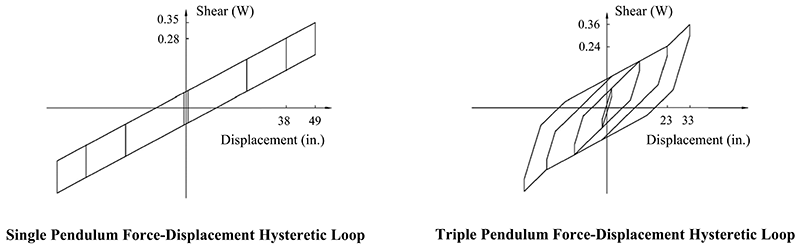
Figure 8. Friction pendulum isolator hysteresis. Courtesy Earthquake Protection Systems.
For the analysis of the sculpture, a two-step process was employed. A finite element model of the sculpture body was used to check local stresses acting on the bronze, particularly around the long openings, and also local buckling (Figure 9). An elastic “stick” model included the full sculpture and base isolators to check global behavior, overall displacements and confirm the finite element model.
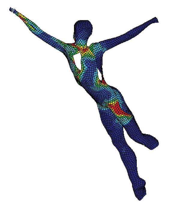
Figure 9. Finite element model of sculpture.
The artist had a small scale model of the sculpture scanned to create a stereolithography (“.stl”) digital file, and the engineers took cross sections from this file in order to calculate member properties for the stick model. For the finite element model, a new mesh was needed because a sterolithography file is made up of elements, many with acute angles, which are not ideal shapes for analysis. The .stl file was brought into the software Rhinoceros in order to create a new 3-D surface, which was then brought into the finite element program to create a satisfactory mesh.
The result of the base isolation and advanced analytical work was reduced bronze thicknesses that the fabricator could accommodate.
Because the base, with its folds and billows, was not an ideal structural shape, a stainless steel pipe was added that rose from the isolators to approximately mid-calf of the load-bearing leg. A “moat cover” of black granite on a steel plate covered the gap provided to accommodate the horizontal movements expected at the base isolators. The structural designers used Tekla to create the fabrication drawings for the sculpture’s steelwork.
Conclusion
The Sanctuary for Sufism Reoriented presented many challenges to its design team, including high seismicity, unusual geometries and a unique sculpture. The project is expected to open in mid-2016, providing an elegant, unique and durable worship space for its congregation, fulfilling a dream decades in the making.▪
Project Team
Structural Engineer: Thornton Tomasetti, San Francisco, CA
Owner and Construction Manager: Sufism Reoriented, Walnut Creek, CA
Design Architect: Philip Johnson/Alan Ritchie Architects, New York, NY
Executive Architect: Soga + Associates, San Francisco, CA
Geotechnical Engineer: DCM Consulting, Inc., Lafayette, CA
Isolator Supplier: Earthquake Protection Systems, Vallejo, CA
Concrete Contractor: Overaa Construction, Richmond, CA
Sculpture Fabricator: Mussi Artworks Foundry, Berkeley, CA