
The Bollman Truss was the first widely adopted cast and wrought iron railroad bridge in the United States. It was designed and patented by Wendel Bollman (STRUCTURE, February 2006) on January 6, 1852 after he built several on the B&O Railroad. Richard Osborne built an earlier iron bridge in 1845 on the Reading Railroad at Manayunk, a portion of which is now on display at the Smithsonian Institution in Washington. It consisted of three cast iron trusses with wrought iron verticals. James Milholland also built a 50-foot long wrought iron riveted girder bridge for the Baltimore & Susquehanna Railroad at Bolton Station in Baltimore in 1846.
As Bollman’s patent application drawing shows, it could be built either as deck or a through truss. As in the Whipple Bridge (STRUCTURE, December 2014), all compression members were of cast iron and all tension members of wrought iron.
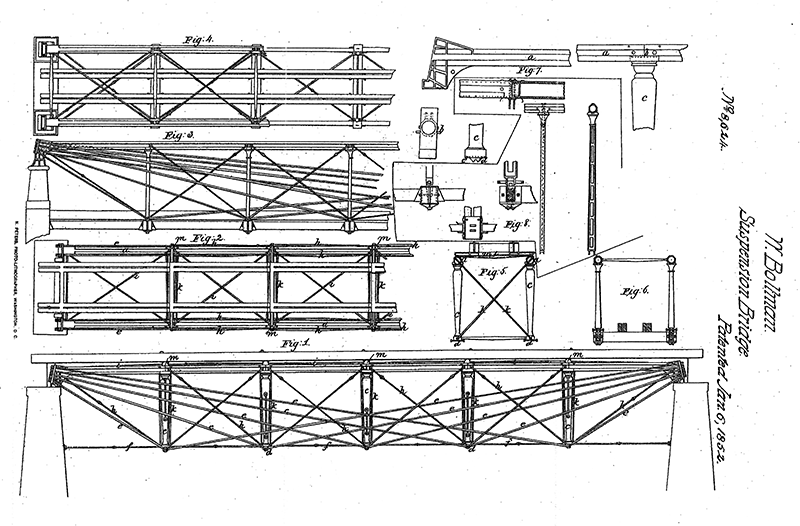
Bollman Patent No. 8,624.
He called his top compression chord a “stretcher” that could be built of iron or wood. If of iron, he recommended hollow tubes. His cast iron verticals, struts, which had different shapes for the deck or through versions, had a “shoe” at the bottom under which an eyebolt projected to pick up diagonal wrought iron bars that ran from the bottom of the strut up to each end of the stretcher. In addition, he had cross bracing in each panel to retain the geometry of his truss. He wrote in his patent application,
“This bridge has the advantage of great strength and perfect security, with very little weight of metal; all the forces can be calculated with absolute certainty, and without complicating the problem; and the structure is so simple, that all the wrought iron work can be executed by the commonest blacksmith. The bridge has been thoroughly tested, and fully proves the correctness of the principles upon which it is based.”
In other words, it was just the opposite of Whipple’s truss that used a lower chord tension member to keep the thrust of the arches from spreading the ends, in that he used top chord compression member to keep the tension ties from pulling the end of the truss inwards. Knowing Whipple’s method of determining the force in each member, he could size them efficiently. Whipple, however, in his book, determined that the most efficient angle for any tie in a truss was 45°; Bollman, especially in long trusses, had some very flat angles on his ties, thus reducing their efficiency.
Bollman began his bridge building career as a carpenter on the B&O Railroad in 1837, working on Benjamin Latrobe’s and Lewis Wernwag’s Harper’s Ferry Bridge (STRUCTURE, August 2014). By 1840, Bollman was named by Latrobe to be “Master of Road” that placed him in charge of all bridges on the line. Some time late in the 1840s, Wendell looked into the design of an iron bridge. Trussed beams had been utilized for years but usually consisted of one beam, one vertical post and a wrought iron bar dropping from the ends of the beam down under the post. This system created a simple truss. Bollman extended this system by adding several posts to a top stretcher with asymmetric rods supporting the posts. Robert Vogel, in his fine paper on Bollman, wrote, “he was perhaps the most successful of the latter class [self taught]…He may be said to be a true representative of the transitional period between intuitive and exact engineering Actually, his designing was a composite of the two methods. While making consistent use of mathematical analysis, he was at the same time more or less dependent upon empirical methods. For years, B&O employees told stories of his [Bollman’s] sessions in the tin shop of the railroad’s main repair facility at Mount Clair in Baltimore, where he built models of bridges from scraps of metal and then tested them to destruction to locate weaknesses. It seems most likely, however, that the empirical studies were used solely as checks against the mathematical.” Bollman built his first bridge, The Little Patuxent Bridge, near Laurel, Maryland in 1850 and replaced the Winchester & Potomac 124-foot span of the Harper’s Ferry Bridge in 1851. In 1852, he built his third bridge at Bladensburg, Maryland over the Anacostia River. Many others followed in the 1850s and 1860s, but this article will primarily discuss the Harper’s Ferry Bridge across the Potomac River.
The B&O Railroad and the Winchester & Potomac Railroad built their covered wooden bridge directly across the Potomac River in 1837. Several years later, the B&O built a “Wye” span to continue its line to the west. In 1850, they decided to upgrade the westerly span, sometimes called the Washington Branch, and chose to utilize the Bollman design, as the Little Patuxent Bridge had proved satisfactory. It was a through span to match the existing wooden spans. They built three masonry towers, rather than cast iron towers, on the end pier and the westerly abutment to support the span. Bollman wrote a pamphlet on this span entitled, Iron suspension and trussed bridge as constructed for the Baltimore and Ohio Rail Road Co. at Harper’s Ferry, and on the Washington branch of this road. That was published by John Murphy and Company in Baltimore and dated 1852. Bridge engineers used pamphlets in those days as a means of advertising their designs and showing their cost effectiveness.
In his pamphlet Bollman wrote,
“This bridge was erected in 1852, from the designs of Wendel Bollman, C.E., Inspector of Repairs, Baltimore and Ohio Railway. The span is 124 feet between abutments. The length of cast-iron in stretcher, 128 feet. The weight of cast-iron in the R. R. truss, 65,137 lb.; of wrought-iron, 33,627 lb.; making a total weight of cast and wrought iron, 98,664 lb.
The wrought-iron requires little workmanship, the rods from the centre to abutments having but an eye at one and a screw at the other end, with a weld or two between according to length. The long counter-rods have two knuckles and one swivel for adjustment of strain and convenience in welding, as well as in raising the whole.
The cast-iron stretcher is octagonal without, circular within, and averages one inch of metal. It is cast in lengths according to the length of panel, and jointed in the simplest manner; at one end of each length is a tenon, at the other a socket. The latter is bored out, and the tenon and its shoulder turned off in a lathe to fit the socket; thus, when thoroughly joined, to form one continuous pipe between abutments. The ends of the sections of cylinders, inserted to those contiguous, are slightly rounded, to allow a small angular movement without risk of joint fracture…
This system, perfect in itself, is additionally connected by diagonal rods in each panel; also by light hollow castings, acting as struts. The diagonal side rods might be safely dispensed with, for the peculiar merit of the truss is its perfect independence of such provision. They are therefore used as a safeguard only in case of the fracture of any of the principal suspension rods.
By this combination of cast and wrought iron, the former is in a state of compression, the latter in that of tension, – the proper condition of the two metals. It unites the principles of the suspension and of the truss bridges. Each bar performs its own part in supporting the load in proportion to its distance from the abutment; so that the entire series of suspending rods transmits the same tension to the points of support as would be equally transmitted from thence to the centre of bridge…”
And after presenting his method of analysis he concluded,
“This bridge, it will be seen, is composed of seven independent trusses, which transfer the weight concentrated on each floor beam directly to the abutments, without aid from any other connection; and not from panel to panel, as in general use…
In case of fire, the floor may be entirely consumed without any injury to the side truss…
In an experiment undertaken to prove the rigidity of this structure, three first-class tonnage engines, with three tenders, were first carefully weighed, and then run upon the bridge, at the same time nearly covering its whole length, and weighing in the aggregate 273,5501b. or 136 1850/2000 tons nett, being over a ton for each foot in length of the bridge.
From this test it was found, according to gauges properly set and reliable in their action, that the load did not cover the entire length of bridge by about 13 feet, yet the excess of weight in the middle, and at a speed of about eight miles per hour, produced no greater deflection than 1-3/8 inch at the centre post, and 9/16 inch at the first post from abutment.”
Squire Whipple didn’t like it, writing in the American Railroad Journal that it was, “a sort of mongrel bridge, something between a Suspension Bridge and a truss bridge and partaking in a measure of the character and qualities of both…” He had discussed a similar idea in his 1847 book but concluded, “it was fully and conclusively demonstrated, that the main principle and idea involved was utterly worthless, as it regarded Truss bridges. Not meaning that a safe and useful bridge cannot be made in this way; but that it can only be done at a much greater expense than is required to make an equally safe and useful bridge, on other plans and principles.” It was, he wrote, “A mere fossil of one of Whipple’s discarded principles.” Herman Haupt, however, who headed a committee to report on the bridge, wrote, “the bridge constructed by Wendel Bollman possesses every essential requisite of an efficient structure, and that no arrangement of parts in general use can be considered superior to it, or promising more satisfactory results.”
The bridge remained with a single iron span and 7 wooden spans until June 14, 1861. when General Joseph Johnston blew up and burned the wooden spans as he evacuated Harper’s Ferry early in the civil war. The only thing remaining was the Bollman Truss and the piers. The military then built a pontoon bridge for their use and the B&O built a wooden trestle for their purpose. In July and August 1862, the B&O replaced some of the trestlework with two Bollman spans. Shortly after, the reb’s burned the bridge again when retreating from the battle of Antietam on September 18, 1861. The B&O then built three Bollman spans in September and November 1862. On July 20, 1863, the Yankees burned the bridge when Lee was invading the north on the way to Gettysburg. The bridge was rebuilt and in July 1864 General Jubal Early burned it after his failed invasion of the north that was stopped outside of Washington after a battle at the Monacacy River. After the War in 1868, the bridge was entirely rebuilt with Bollman iron trusses.
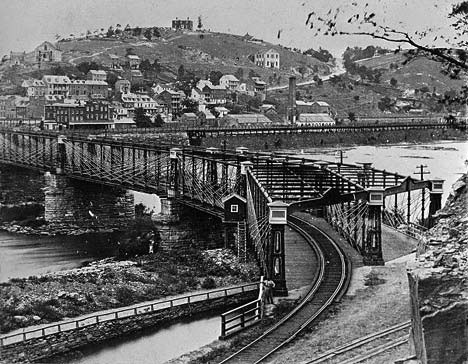
Harper’s Ferry Bridge post 1868 from Maryland side, C&O Canal in foreground. Courtesy of HAER.
The Winchester Span was documented by the National Park Service’s Historic American Engineering Record (HAER) (WVA, 19, HAER, 28) based upon iron retrieved from the river after the 1936 flood that washed away the entire bridge, and early drawings by Bollman. Bollman trusses were used on many B&O bridges, as well as approach spans in two major Mississippi River crossings at Quincy, Illinois and Bellaire, Ohio and at Clinton, Iowa as a swing bridge. The only surviving Bollman Bridge is at Savage Station in Maryland across the Little Patuxent River. It was originally built in 1869 for the B&O and moved to its existing site in 1887 and is used only for pedestrians. It was documented by HAER in 1985.
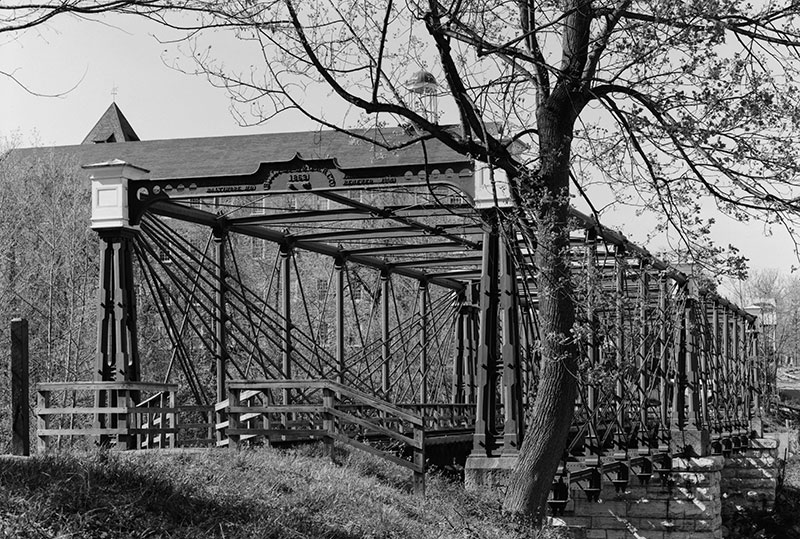
Bollman Bridge, Savage, Maryland. Courtesy of HAER.
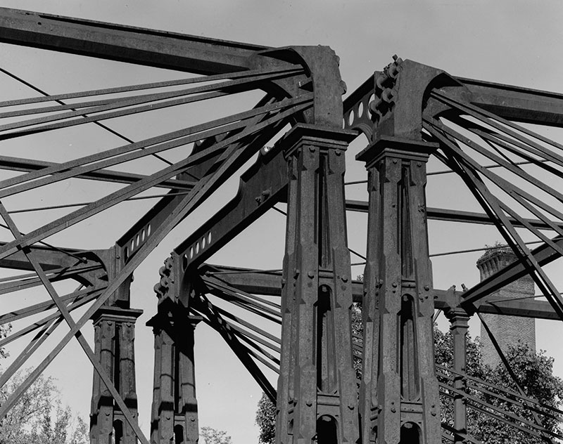
Bollman Truss, cast iron columns and top chord, wrought iron diagonals. Courtesy of HAER.
Bollman’s plan was widely used as a cast and wrought iron railroad bridge between 1850 and 1870, especially on the B&O Railroad, but was generally replaced starting in the late 1870s by Fink and Whipple Iron Double Intersection Trusses that made a more efficient use of the iron.▪