
As described in the August edition of STRUCTURE® magazine, Phoenix Sky Harbor International Airport opened the first stage of their automated transit system, PHX Sky Train™, on April 8, 2013. Thousands of passengers have already boarded the Sky Train and experienced the comfortable five minute ride from the 44th Street Station through the East Economy Lot Station, over Taxiway “R” (more than 100 feet above Sky Harbor Blvd.), ending at Terminal 4.
The next phase, known as Stage 1A, is currently under construction and continues Sky Train’s route from Terminal 4 to Terminal 3. Scheduled to be open in early 2015, Stage 1A, similar to the Stage 1 construction, faces the task of crossing an active taxiway. Unlike the first Stage’s crossing above Taxiway “R”, the current phase of construction crosses beneath Taxiways “S” and “T”. Both Stages’ taxiway crossings presented several design and construction challenges.
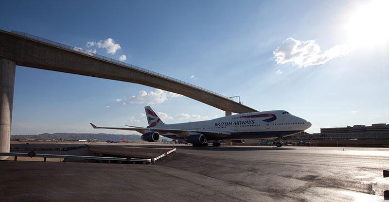
British Airways 747 crossing beneath the Taxiway “R” bridge, June, 2012. Courtesy of City of Phoenix Aviation Department.
The World’s First
On Oct. 10, 2010, a celebration to mark the re-opening of Taxiway “R” was held by the City of Phoenix with members of the City’s Aviation Department, designers, contractors and media watching as the first two planes taxied under the new bridge. Nowhere in the world had this been done before, a bridge carrying trains over an active taxiway; even more remarkable, a taxiway that handles planes as large as Boeing 747’s. Delivered a week ahead of schedule and approximately 35 percent below the initial budget, there was reason to celebrate. To make this crossing a reality, creative problem solving by both design and construction teams was necessary.
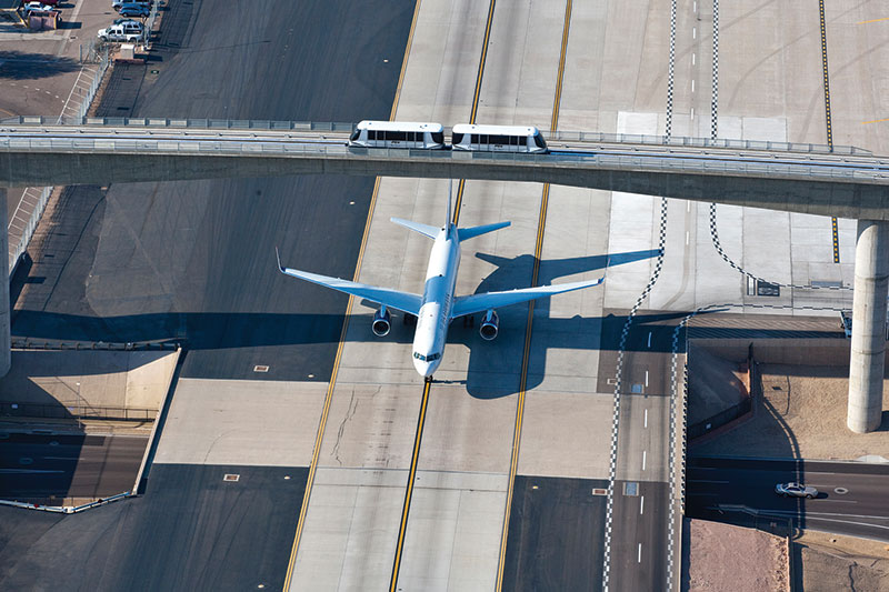
A US Airways jet passes beneath the Taxiway R crossing with the PHX Sky Train overhead. Courtesy of City of Phoenix Aviation Department.
Design Constraints
An area 340 feet in length and 75 feet in height above Taxiway R was needed to provide the clearance required for Group V Aircraft (Boeing 747’s). Additionally, to stay below the Part 77 surface established by the Federal Aviation Administration for safe aircraft operations, the height of the bridge was limited. Thus, a narrow vertical band of approximately 40 feet remained within which the bridge could be built. Taking into account the vertical curve and bridge barrier, the vertical band reduced further to just over 30 feet.
In addition to the challenging geometry was the schedule constraint for constructing the bridge. Because the construction required the taxiway to be closed, a limited shutdown period of six months was possible due to airport operations. The timing of the shutdown was an additional factor to be managed. Due to seasonal traffic volumes, the closure had to occur between Spring Break and Thanksgiving. If this window was missed, it would delay construction of the bridge, which would delay the entire project. Obviously, it was critical to choose the correct structure and get the design and construction right the first time.
Eight alternatives were evaluated and ranked based on impacts to the taxiway, long-term maintenance, cost, aesthetics and special considerations specific to each structure type. Evident from a drive on metro-Phoenix’s freeway system, concrete box girders are a popular choice, which require little maintenance, only routine inspection and, in many cases, a lower life-cycle cost. Aesthetically, the box girder was the most streamlined and least obtrusive choice, fitting nicely with surrounding concrete structures and adjacent guideway. Thus, a cast-in-place box girder bridge was chosen.
Concern arose regarding the cost of falsework supporting a superstructure 90 feet above grade during construction. In order to minimize disruption to the taxiway, end spans (which did not require a taxiway shutdown) would be constructed first. To reduce falsework cost, the CM-at-risk contractor recommended that the designers determine a way to re-use the end spans’ falsework for main span construction. Design based on this concept was completed in July, 2009.
The contract to build the bridge was awarded in September, 2009. With the demand for construction impacted by the recession, the bridge contractor found an abundant supply of falsework material, and proposed supporting all three spans simultaneously until post-tensioning was complete. Therefore, the elements added to accommodate the reuse of falsework were no longer necessary. A redesign of the bridge, which eliminated supplemental post-tensioning and closure pours, was completed in three weeks; a quick turnaround to keep construction on schedule.
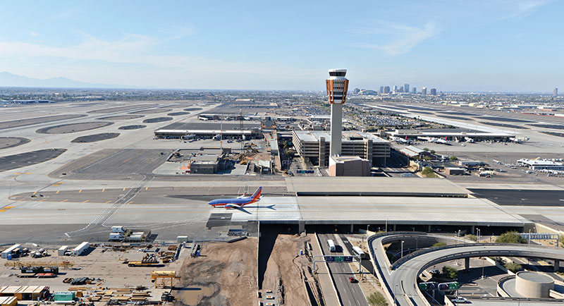
A Southwest Airlines 737 crosses over the newly completed Taxiway “S” bridge. Courtesy of Visions in Photography.
Construction Phase Challenges
Tight construction clearances were common and unavoidable during construction. While the taxiway remained open, construction began with pier foundations. Due to the close proximity of traffic on Sky Harbor Blvd and a bridge over a nearby local street, the foundation for the eastern main pier proved particularly difficult to construct. This was overcome by installing the drilled shafts from existing grade, rather than excavating first and drilling from the bottom of footing grade as conventionally done. A trench filled with slurry was placed to form the perimeter of the pile cap to allow for the 10-foot deep cap excavation without impacting the adjacent area.
Another challenge encountered while building the superstructure was in forming the deepest sections of the webs near the main piers. Because the webs tapered in thickness, working space for forming and stripping became extremely limited (as shown in upper right graphic). Once the floor and webs of the girders for the end spans were constructed, the taxiway was shut down in April 2010 to begin the construction of the main span. The deck was poured continuously over all three spans, and post-tensioning of the bridge occurred in early September 2010.
Arguably the biggest challenge to construction was the tight and unmovable schedule. It required tremendous planning efforts that included several hour-by-hour internal schedules for weekend and critical activities, such as falsework lowering. Executing necessary restrictions on Sky Harbor Blvd. and surrounding roadways, required countless emails and hours of phone calls to communicate between contractors, airport operations, airlines, vendors, and the travelling public. Crews worked through most holidays and weekends, and out of 307 available shifts, the contractor worked 272 shifts or nearly 90 percent of the total time available.
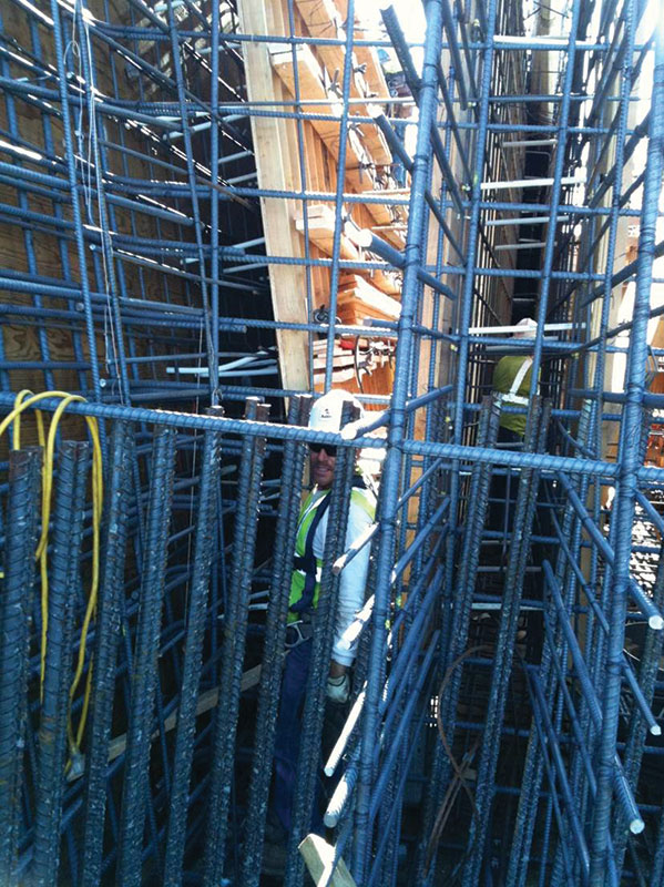
A construction worker within the tight clearances of Taxiway “R”. Courtesy of Hensel Phelps Construction Co.
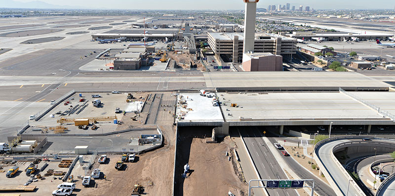
Taxiways “S” & “T” Going Below the Surface
In contrast to the highly visible crossing above Taxiway “R”, the crossings below Taxiways “S” and “T” will be invisible to all but the passengers on the Sky Train. Why cross above one taxiway only to then cross beneath another two? Extensive coordination and planning determined that an elevated Taxiway “R” crossing provided the optimal alignment into the Terminal 4 Station. Additionally, the amount of utility relocation required by constructing beneath the taxiway made that option infeasible. Utility relocations, while a concern, weren’t as problematic at Taxiways “S” and “T”. However, because the two taxiways, at 210 feet wide, are only separated by 50 feet; placing a pier between them would violate clear zone requirements. The resulting span length would be 600 feet, a superstructure capable of that span, apart from being uneconomical would have been impossible to fit in the narrow vertical band described for the Taxiway “R” crossing.
Phoenix Sky Harbor International Airport has been the city’s airport since 1935, so the existence of underground utilities that are unaccounted for, abandoned and forgotten, or located incorrectly on utility maps is not surprising. While understandable, the potential consequences of unknown utility lines directly conflicting with new construction can be disastrous. Instances of unforeseeable conflicts arose in Stage 1 construction, which cost several weeks of construction time to resolve. With only a six month construction duration for each undercrossing, a delay due to a hidden conflict could disrupt the schedule for the entire project and, more importantly, the operations of the airport which requires that all taxiways be open from Thanksgiving to New Year’s day.
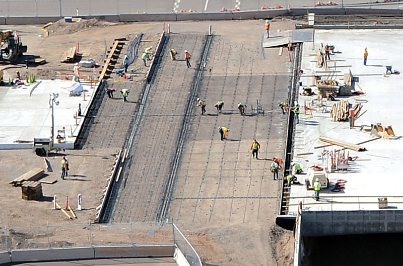
Work on the Taxiway “S” anchor slab. Courtesy of Visions in Photography.
Design Innovation
To mitigate the risk of utility conflicts, the designers took an innovative approach to the undercrossing design. The design contemplated adding a new span on the south end of each taxiway. Typically, construction for a new bridge abutment would require a large amount of excavation and thus greatly increase the chance of uncovering unknown utilities. Therefore, the designers developed an abutment wall consisting of 54-inch diameter drilled shafts approximately 50 feet long at 10-foot spacing, restrained at the top by an anchor slab and with the gap between each shaft filled with a reinforced shotcrete wall. This allowed the new abutment to be built with no excavation behind the drilled shafts, except for the shallow depth required for the anchor slab shear keys.
Another innovative idea that mitigated schedule risk was to use the existing taxiway bridge abutment as a support for the new span. The initial design proposed building a new pier adjacent to, but outside the footprint of the existing abutment, with a reinforced concrete slab to span the short gap between the two supports. During final design, this concept was eliminated after determining that loading from the new span would cause less stress than the fill behind the existing abutment. With a relatively small amount of concrete added to the existing abutment to accommodate the new span, the duration of construction was shortened.
As required by Airport Operations, only one taxiway could be shutdown at a time. Construction began with Taxiway “S” on May 22, 2012 and was completed five days ahead of schedule on November 14, 2012. The new superstructures were built using the “soffit fill” technique, where the superstructure was built directly on compacted fill and, after post-tensioning, the fill is excavated to reveal the soffit of the bridge. This technique also contributed to shorter construction durations. Taxiway “T” was shut down on January 7, 2013 and was re-opened with its new span on June 11, 2013, three weeks ahead of schedule. The cost for both undercrossings came in approximately ten percent below the initial budget.▪