
Department of Defense (DoD) facilities have never had a more complex set of protective needs than they do today. Following the Sept. 11, 2001 attacks, the DoD published its Unified Facilities Criteria (UFC) 4-010-01, DoD Minimum Anti-Terrorism Standards for Buildings. In 2013, this document was updated to its current version. UFC 4-010-01 identifies what reasonable precautions can be taken – for a reasonable cost – on buildings owned, leased, privatized or otherwise occupied, managed or controlled by or for the DoD. It also prescribes methods for achieving the desired level of protection. The document indicates that it is most cost effective to address anti-terrorism force protection (AT/FP) during design and early construction, rather than to retrofit facilities. Tilt-up construction offers one sound approach to accommodating AT/FP from the outset of building design.
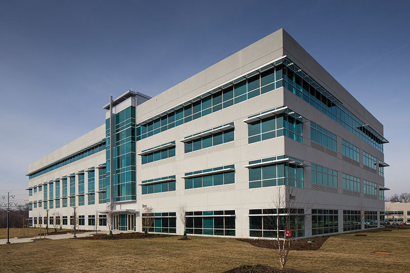
Building completed in 2013.
Reasonable Protection
Because it would be impractical to provide a level of protection that would guard against every possible situation, UFC 4-010-01 standards seek to minimize the likelihood of mass casualties in the event of an unforeseen terrorist attack. Table 2-1, Levels of Protection – New and Existing Buildings outlines the varying levels of protection and the potential building damage/performance associated with each level. The table also presents resultant potential injury. A secondary document, UFC 4-023-03, Design of Buildings to Resist Progressive Collapse, sets design criteria to prevent disproportionate collapse of structures with three or more stories. The goal of UFC 4-023-03 is to produce structural systems that limit the effects of localized failure and prevent the spread of damage from element to element. The required design level of resistance to progressive collapse is determined by the building’s Occupancy Category (OC) in accordance with UFC 4-023-03 Table 2-2, Occupancy Categories and Design Requirements.
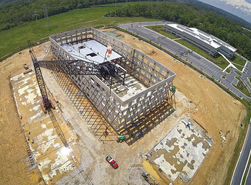
Aerial view of steel erection in progress.
A Maryland Facility Provides a Proving Ground
Tilt-up concrete, long recognized as a quick and economical building method, is now being proven as a means of achieving high levels of blast force protection and progressive collapse resistance. A four-story building constructed in 2013 in Maryland near the nation’s pre-eminent center for information, intelligence and cyber security provided a test case for the AT/FP abilities of tilt-up design.
The building was built on a speculative basis, which is not common for an AT/FP structure because of the increased upfront costs. The tilt-up design achieved cost savings that made it feasible for the developer to include AT/FP in the initial design, thus improving the building’s marketability to government or federal contractor user groups. This building is part of a larger campus of buildings with similar performance capabilities.
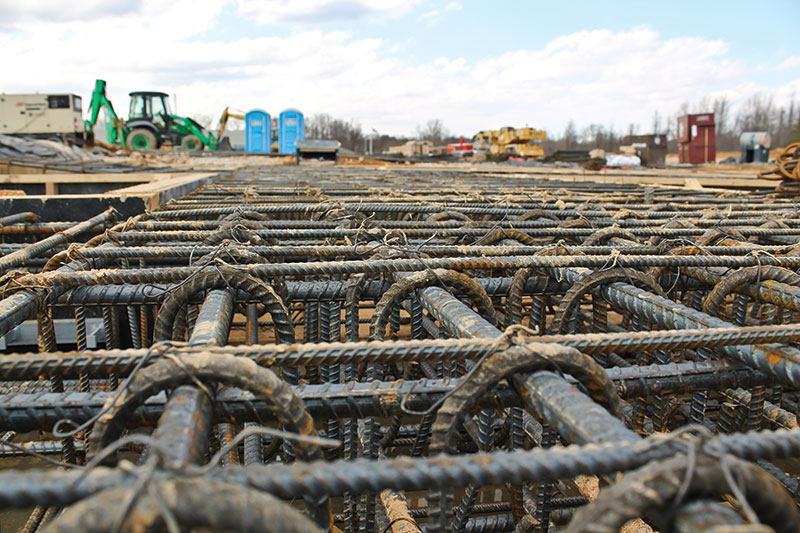
Panel leg reinforcement. Additional stirrups at first floor for ELR requirements.
The building was built as a joint venture between Konterra Realty and Boston Properties, and is a product of extensive, ongoing research conducted by Hinman Consulting Engineers, Powers Brown Architecture, Cardno Haynes Whaley and Harvey-Cleary Builders. This group developed a research case study in 2011 in which the design of an existing office building was modified to determine whether it was feasible to apply the UFC requirements for blast and progressive collapse resistance at a medium level of protection. At this level of protection, the building would potentially experience minor, economically repairable damage resulting from an attack of given magnitude. The outcome of that study confirmed that tilt-up design could be used to achieve force protection for blast and progressive collapse resistance without perimeter columns. The research suggested that the premium for a tilt-up building incorporating medium level of protection was expected to be around $15 per square foot more than conventional construction methods without these capabilities.
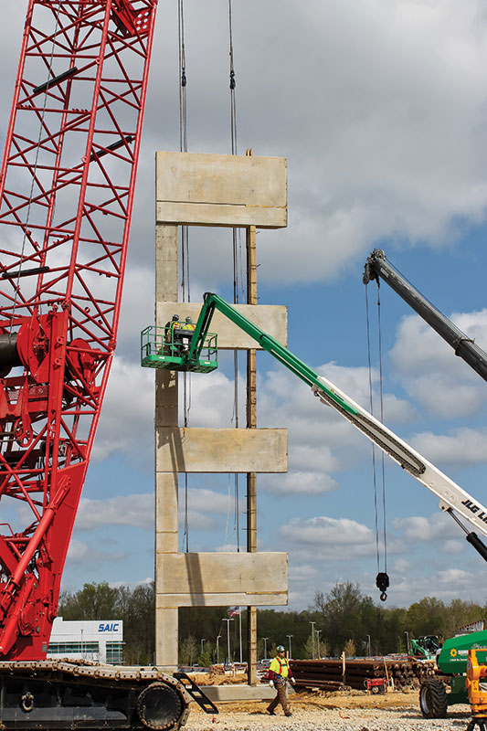
Erection of corner panel with strongbacks.
Working through the Details
To apply the UFC 4-010-01 criteria to the design of the Maryland building, building elements were analyzed individually to check their ability to withstand an air-blast load as determined by the design basis threat at the appropriate standoff distance. (Standoff distance is the distance maintained between a building and the potential location for an explosive detonation). The site was intentionally designed with constraints to maximize standoff distance, which is the most effective way to protect a structure from an exterior explosive threat.
The project was classified as OC III, which includes both an Alternate Path (AP) requirement and an Enhanced Local Resistance (ELR) requirement to resist progressive collapse. The AP method is described in the document as often being the most practical approach for load-bearing wall structures. Essentially, this method requires the structure immediately adjacent to a damaged area to be able to transfer loads around the affected area down to the foundation, thereby isolating the failure and avoiding the spread of damage. ELR requires that the shear capacity of each first floor wall and its connections to the building diaphragms exceed each wall’s flexural capacity to prevent a brittle-type failure from an extreme event at the lowest structural level.
The Maryland building consists of 32 four-story tilt-up concrete panels, typically 30 feet wide and 64 feet tall. The tallest panel is 68 feet tall and weighs 125 tons. The minimum panel structural thickness was determined to be 11 inches for blast and progressive collapse resistance. The typical overall panel thickness was increased to 15 inches to allow the panel legs to maintain this minimum structural thickness behind a continuous window strip with 4-inch deep mullions that wraps around the entire building perimeter at the fourth floor. This continuous window strip gives the appearance of a ribbon window from the exterior, enhancing the aesthetic appeal of the building and masking the tilt-wall nature of the structure.
The foundation system consists of shallow spread footings supporting interior columns and a continuous wall footing at the perimeter supporting the wall panels. In addition to in-service gravity and lateral loads, the perimeter footing was designed for construction loads and progressive collapse loads. For construction loads, the footing was designed for the case when the panel weight is concentrated at bearing channels at each end, rather than the more uniform distribution of panel loads after grouting under the panel. For progressive collapse loads, the footing was designed to take additional load locally from redistribution of building loads if any panel leg was removed in a progressive collapse scenario.
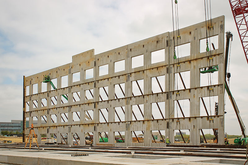
Erected panels from the building interior. Embedded plates at each panel joint will be connected for progressive collapse resistance.
AT/FP requirements influenced the structural design in many ways. The progressive collapse requirement was a factor influencing the decision to use full-height panels with a 30 foot module for the panel width. Limiting panel joints limited instances of discontinuity that needed to be bridged with large steel connections. Dowels cast into the wall panels at the first floor were designed to resist tension from a blast force that would result in the panel pulling away from the building in a rebound response during a blast event. Similarly, the connections of continuous deck edge angles to embedded plates in the wall panels at each elevated floor were designed to resist out-of-plane panel loads caused by blast forces. Beams are connected to plates embedded in the tilt-wall panels by double-angle shear connections with horizontally-slotted holes for construction tolerance and thermal expansion. Kickers at each panel leg at each floor just above the window head also help to tie the panels back to the diaphragm to distribute the blast loads and meet progressive collapse requirements. Due to the load bearing nature of the wall, the wall systems are designed to remain elastic when subjected to the blast loading. The analysis was performed via Hinman’s developed software BAM®.
Lightweight concrete on metal decking was chosen as the floor system at each level to reduce the weight of the structure, thereby contributing to the reduction of progressive collapse load. Due to pressures from blast loads, the roof structure consists entirely of wide flange steel beams instead of an open-web steel joist system, as would be more typical for conventional construction. Beams were spaced at 10 feet on center, similar to the floor beams at intermediate levels. Therefore, a 3-inch deep steel deck was used to accommodate the longer span between supports.
Lightweight concrete mixes were used for the panels to reduce weight and enable the panels to be erected with an economical crane. Embedded plates in the panels have reduced capacity in lightweight concrete per ACI Appendix D. Therefore, to keep the sizes of embedded plates manageable, 6,000-psi concrete was used for the tilt-up panels to increase the capacity of the connections to meet blast and progressive collapse loads.
Perhaps the most unique elements of the design are the panel-to-panel connections at each panel joint, which are designed to allow loads to redistribute in a progressive collapse scenario while still permitting in-plane movement of the panels under service conditions. Traditionally, tilt-up panels are not connected to one another except, perhaps, at the corners of a building. In older tilt-up structures, where connecting panels was more common, concrete shrinkage and basic thermal movement often caused these connections to either fail or damage the concrete wall. Because of the Alternate Path requirement for this project, the design team utilized large plates spanning across panel joints and connected to embedded plates in each panel to tie the structure together. There are four embedded plates on each side of each panel. The large embedded plates, each up to 5 feet tall and 18 inches wide with up to 20 headed studs, weighed on average 300 pounds and had to be set by mobile crane. The panel connections alternated between a connection plate welded to the embedded plates on each side of the joint and a connection plate welded to the embedded plate on one side of the joint, and fastened with a bolted slip connection on the other side of the joint. This alternating pattern continued around the building, allowing for in-plane movement of the panels.
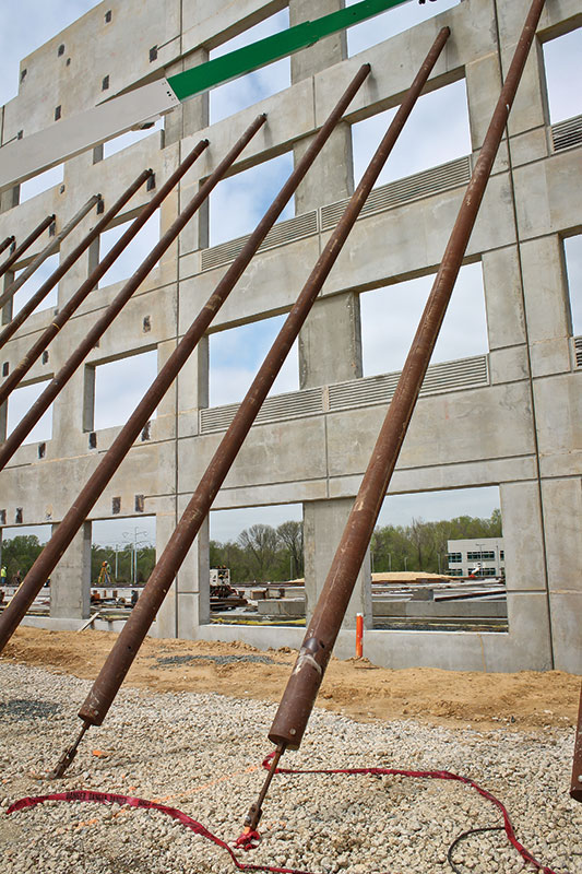
Panel exterior face with temporary braces during construction.
There were approximately 1,370 embeds in 32 panels, not including the window anchor blast embeds for 208 openings. In addition to the weight of some of the embeds, the density of the steel reinforcement made setting difficult. Many panels required more than 14,000 pounds of rebar to be placed, with total panel weights exceeding 248,000 pounds. The size and weight of the panels, combined with the number of large openings and deep depressions, called for unique lifting and bracing engineering strategies. Full-height double-stacked strongbacks were used to erect the panels where necessary; the strongbacks utilized the existing reinforcement in the panels and reduced the need for additional reinforcement, helping to keep costs to a minimum.
Conclusions
The numerous challenges faced on this project were overcome by collaboration, planning and persistence. This structure serves as a testament to the versatility, economy and strength of tilt-up as a building system, and its ability to meet the diverse needs of a wide array of building requirements. It also provides conclusive evidence that, in the post-9-11 era, tilt-up offers a valuable advantage in terms of AT/FP design.▪