
Balancing blast load design and research with project requirements can be challenging. A simple renovation, like one including window replacement, may seem straightforward especially when seismic rehabilitation is not a concern, but on a West Coast US Military Base it is anything but. Accurately incorporating blast research with what is known about the construction of an existing building is the focus of this article.
The spotlight project is the renovation of four aircraft hangars at a Washington State military base. Two of the four hangars were originally constructed in the 1960s, one in the early 1950s, and one earlier, in the 1940s. Funding for brand-new hangars was not available, but the hangars had many inadequacies that needed to be addressed. For this reason, the A/E team was tasked with the design of the renovation of architectural, mechanical, electrical, security, and structural components that could prolong the life of the buildings and ensure they meet the mission requirements of present and future users.
Blast Requirements
Requirements for blast protection design on military bases are governed by the Department of Defense (DoD). Criteria for various security related measures are provided by the Unified Facilities Criteria (UFC), administered by the United States Army Corps of Engineers, Naval Facilities Engineering Command, and the Office of the Air Force Civil Engineer.
DoD Minimum Antiterrorism Standards for Buildings, UFC 4-010-01, February 2012, is only required on existing buildings “when triggered” (Section 1-8.2). The replacement cost was not exceeded by more than 50% which would normally trigger a blast upgrade. However, the four hangars triggered the requirement of this standard with the Window, Glazing, and Glazed Door Replacement portion of the project. As required, Appendix B Standards 10 and 12 were used for the blast design.
Blast Loading
Characteristics about the environment in which the threat exists are key to blast protective design loading determination.
Accessibility and Proximity of Threat
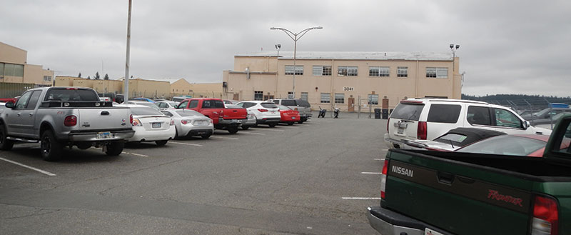
As the four hangars are on a base with a controlled perimeter, per Section 2-4.7 of UFC 4-010-01, the restricted accessibility to the site permits application of a lower blast load. On this project, the proximity of threat varied by hangar and was governed by the distance to the parking lot. This is known as standoff distance. Figure 1 illustrates the building location relative to the parking lot. Figure 2 shows an example of a parking lot adjacent to one of the hangars. Three standoff distances are referenced in the UFC: conventional construction standoff distance (CCSD), minimum standoff distances, and actual standoff distance. If the building meets the requirements of the conventional construction of the UFC and the CCSD distance requirements, then no further analysis is required (Figure 3). These buildings had neither of these and, per the UFC, required dynamic analysis.
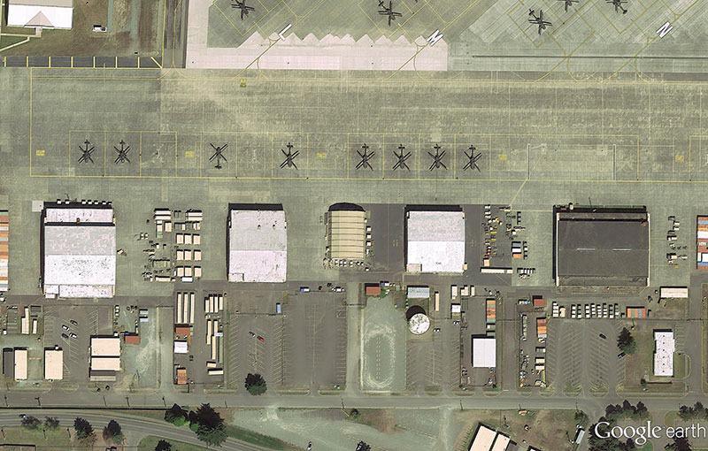
Figure 1. Project’s site and building layout.
- Figure 3. Parking and roadway control for existing buildings – controlled perimeter.
Type and Size of Threat
The explosive weight is the equivalent weight of TNT used to describe an explosive threat. It is defined in the UFC 4-010-01 as Type I, II, or III based on the building classification and the Level of Protection (LOP) for the project. The actual value for the explosive weight is specified in UFC 4-010-02 DoD Minimum Antiterrorism Standoff Distances for Buildings. This document is For Official Use Only and, although the actual weight is used in design, all reports and final calculations must keep the explosive weight confidential. Contractors that require the actual value must provide documentation of US Citizenship and obtain them from the contracting officer on their project.
General Loading on Hangars
Figure 1 illustrates the close proximity of the parking spaces to the adjacent hangars. This layout produced excessive blast demand for windows and subsequently the existing structural members during analysis. Parking spaces are in high demand at this busy military base and direction from the Corps of Engineers project manager was to protect parking. Therefore, mitigating blast by reducing proximity to parking was initially not an option.
Dynamic analysis of windows and structural members on each of the four hangars was completed for the actual standoff distances. After involving a window supplier, standoff on Hangar A had to be increased from 20 to 30 feet to reduce costs associated with blast resistant windows. The removal of 2 parking stalls was recommended for Hangar A in order to increase the actual standoff distance from 20 feet to 30 feet.
Multiple parking locations within range of each building were considered for determining reflective and incidental pressures for each elevation of the hangar that had windows. For window design, the actual standoff distance and applicable explosive weight was provided for the window manufacturer to use during construction. A peak pressure impulse, per ASTM F2247, was provided on the drawings for the door manufacturer to estimate blast pressure loads.
The closest blast threat was at Hangar A and resulted in maximum fully reflective blast pressure for any wall framing. The north elevation of Hangar D had the largest standoff distance, where the computed peak incidental pressure was approximately three times the ASCE 7 static wind load pressures. This resulted in the lowest loading for any of the new wall framing. An angle of incidence is the angle between the surface and the direction of the shock wave propagation. Because the building is normal to almost any point from where the blast threat can come from, the angle of incidence was assumed to be zero. Using the angle of incidence may have reduced the blast load in a few select locations, but was not considered since the cost to detail varying conditions was not efficient for design nor for construction.
Blast clearing, another parameter used in dynamic analysis, “…occurs due to pressure discontinuities at the edges of surfaces that develop when the blast wave impacts a surface… this can result in a quicker dissipation of the blast wave in higher pressure areas.” [USACE PDC-TR 06-08] This was ignored because the length of the building adjacent to the parking lot and the height is large enough that the dissipation of energy is not likely. Assuming no clearing is conservative.
Blast Design
As mentioned, the UFC 4-101-01 directs the designer to use specific methods for dynamic analysis on a variety of structural system solutions. The Protective Design Center (PDC) of the Army Corps of Engineers provides support for the blast protection of military facilities and maintains the recommended tools for dynamic analysis and design, including Single-Degree-of-Freedom Blast Effects Design Spreadsheets, or simply SBEDS.
Because of the extreme event, the SBEDS design philosophy uses the full strength of the structural element to sustain the blast pressures. Computed dynamic behavior and output reactions are nonlinear. To ensure satisfactory dynamic behavior, the inelastic response is limited, resulting in response criteria of a maximum allowable support rotation Ɵ and ductility ratio µ for every structural element. The maximum limits of Ɵ and µ are recommended values provided by the PDC in TR 06-08 Single Degree of Freedom Structural Response Limits for Antiterrorism Design based on the required Level of Protection (LOP) for the building and the type of component (primary, secondary, nonstructural). In this project, a ductility ratio limit of 2 was needed for metal studs, while 3 was the ductility ratio limit for existing columns in the structure.
SBEDS has a cold-formed steel (CFS) and structural steel library with complete, commercially available, stud and steel shapes. Input for SBEDS includes span length, spacing or tributary width, material properties, section properties, blast load parameters, and response criteria.
Cold-formed Steel Stud Wall Detailing
The hangars each consist of a two story attached office with a clerestory above which opens to the hangar bay. The original façade of Hangar D consists of corrugated metal siding while Hangars A, B, and C have corrugated metal siding with precast concrete panels along the bottom half of the first floor and at the ends of the buildings.
The primary objective was to distribute wall loading into the diaphragm and allow for the building mass to react against the blast loading. Two types of CFS framing were needed on this project. For high blast pressures, Hollow Structural Section (HSS) shapes were utilized to transfer blast loads from the CFS framing to the structure. Low-level blast pressure lent itself to CFS studs for the entire wall.
Deflection head and vertical slip details were used to avoid superimposed dead and live load axial demand on CFS studs (Figure 4). This detailing was complicated but allowed for a lighter-weight system. This general connection-type was available in SBEDS.
Figure 4. Deflection head and vertical slip details for CFS stud.
High-level Blast Pressure
HSS framing was needed because the CFS studs could not span the full height individually (Figure 5). Because Hangar D is an historical building, the client wanted to maintain opening size and location during glazing replacement, therefore, HSS was oriented primarily horizontally. Hangars B, C, and D have an architectural precast panel on the first floor that the architect wanted to avoid cutting, so these hangars also required horizontal HSS framing. This permitted the use of CFS by reducing the span length of the CFS framing.
Figure 5. Typical high blast pressure wall.
The horizontal HSS was, in most cases, framed into a vertical HSS to carry loads into the diaphragm. At a few locations, where doors interrupted the framing, this was not feasible and existing W6 columns had to be evaluated for blast load, axial load, and reduced ductility acceptance criteria. The W6 column could only resist the blast loading from a tributary width of approximately 5 feet, and therefore could not be used to resist the load from the full wall.
The CFS studs framed to the underside of the spandrel beam. In most cases, this spandrel was a light weight beam not capable of resisting lateral loading from the reaction of the studs. New braces were designed to carry the load to the diaphragm by way of a cover plate. The cover plate was needed to enhance the gravity capacity, but primarily it was needed to distribute the lateral blast demand to the new bracing elements (Figure 6). Additional consideration had to be made when designing connections, since welding to older steel can sometimes be problematic. Bolting was specified wherever possible.

Figure 6. Bottom flange bracing detail.
Low-level Blast Pressure
CFS studs framing the full-height of wall (Figure 7) were utilized where blast pressures were low enough. Built-up sections, up to four S and T shapes, were needed at window and door jambs to transfer the reactions from the glazing. This required careful input and special evaluation to use SBEDS. Bracing was required similar to the walls with HSS framing to distribute load to the metal roof deck and/or wood diaphragms (Figure 8). The design was primarily controlled by the capacity of the existing diaphragms.
It was unclear if research was available on performance of connection details, and some assumptions had to be made for the input based on our specific type of connections.
Figure 7. Typical lightly loaded wall.
Figure 8. Brace at lightly loaded wall.
Conclusion
Building renovations can often be challenging and solutions are atypical. A balance has to be made between the goals of the project, what the code requires, what’s best for the client, and your desire to want to tear down the building and start over. In a blast design project, the process can be enriched with the following lessons learned:
- Always determine what the blast requirements may be during the preliminary stages of a project. Verify blast threat proximity, requirements, and project parameters to ensure that your client knows the level of effort required.
- Involve a window manufacturer with knowledge of blast design for glazing during the early stages of your project. Your glazing (i.e. glazing type, thickness, panes) and blast criteria may change based on input from a glazing specialist. The glazing type can also drastically change the loads carried through to the rest of the structure.
- Determine the façade on your project including possible historical requirements to maintain existing aspects, and assess blast threat and develop demands for each unique façade on the project (Figure 9).
- Group demands into framing types, detailing needs, and typical CFS framing to minimize design and construction effort. Also, review the original construction documents to understand structural conditions and load paths for the building early in the project timeline.▪
Figure 9. Historical Hangar D BIM model.
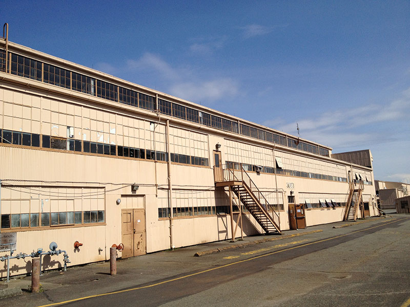
Figure 10. Hangar D. Historically significant structure construction, date unknown.
References
1) USACE PDC Technical Report, PDC-TR 06-08 Rev. 1 January 2008, Single Degree of Freedom Structural Response Limits for Antiterrorism Design
2) USACE PDC Technical Report, PDC-TR 10-02 April 2012, Blast Resistant Design Methodology for Window Systems Designed Statically and Dynamically
3) USACE PDC Technical Report, PDC TR 06-01 Rev. 2 December 2012 Methodology Manual for the Single-Degree-of-Freedom Blast Effects Design Spreadsheets (SBEDS)
4) DoD Unified Facilities Criteria UFC 4-010-01 February 2012, DoD Minimum Antiterrorism Standards for Buildings
5) DoD Unified Facilities Criteria UFC 4-010-02 February 2012, DoD Minimum Antiterrorism Standoff Distances for Buildings FOUO