
The safety of exterior elevated decks, balconies and porches is an important national issue due to numerous documented structural collapses that have resulted in serious injuries and, in some cases, deaths (Shutt 2011; Legacy Services 2010). The problem is not confined to residential construction, as decks are also popular in commercial structures. Due to larger occupancies, the stakes are even higher in commercial construction as evidenced by deck collapses in Polson, MT casino with 52 injured in 2004 and a Miami, FL sports bar with 24 injured in 2013. Engineered design has been hampered by knowledge gaps on structural loads – especially lateral loads. This information is vital for registered design professionals to create safe and efficient engineered designs for decks, porches and balconies.
Vertical loads on decks, such as occupancy and snow, are straightforward to calculate using the provisions of the 2012 International Building Code (IBC) and ASCE/SEI 7-10 Minimum Design Loads for Building and Other Structures (ASCE 2010); however, determining lateral loads on decks is more challenging. Wind and seismic loads can be calculated using the provisions of ASCE 7-10. Lyman et al. (2013a; 2013b) demonstrated the ASCE 7-10 methodology for wind and seismic loads through example calculations for a 12 x 12 foot deck. They found that while wind loads generally control over seismic, the wind loads would not pose much of a design challenge except for hurricane and special wind regions. Of course, the results of the analyses would vary for decks with different sizes and aspect ratios.
The building codes and ASCE 7-10 are silent on the subject of lateral loads due to occupant movement, with the exception of grandstands, bleachers, and stadium seating. This article describes laboratory experiments on full-size decks with two types of occupant loadings: cyclic side-sway and impulse (run and jump stop). Results indicate that lateral loading from occupants will often exceed the worst-case loads from either wind or seismic. The key point being that occupant loading can occur on any deck, anywhere.
Preliminary research at Washington State University revealed that forces generated by occupants are significant, and in many cases greater than wind or seismic forces. The objective of this study was to quantify lateral loads caused by dynamic actions from the occupants. Two deck configurations and two dynamic load cases were investigated:
- Deck Configuration 1: Deck boards oriented parallel to the ledger
- Deck Configuration 2: Deck boards oriented 45 degrees to the ledger
- Load Case 1: Cyclic
- Load Case 2: Impulse
It was expected that the two deck board orientations would result in dramatically different stiffnesses in the lateral loading plane since according to the ANSI/AF&PA Special Design Provisions for Wind and Seismic (AWC 2008), diaphragms and shear walls sheathed with diagonally oriented boards compared to horizontal boards results in a four-fold increase in stiffness. The two dynamic load cases were chosen to represent the types of occupant behavior that might result in the greatest lateral loads. The full details of the research reported herein can be found in Parsons et al. (2013b).
Background
The 2009 (IBC) and the ASCE/SEI 7-10 are silent on the subject of lateral loads from occupants, with one exception. Table 4-1 in ASCE 7-10 gives gravity loads for reviewing stands, grandstands and bleachers, along with Footnote k which stipulates lateral loads of “… 24 lbs per linear feet of seat applied in the direction parallel to each row of seats…”. Footnote k was based on empirical research by Homan et al. (1932) where the lateral forces caused by the movement of a group of people on a simulated grandstand were studied. The lateral load provision in Footnote k is a convenient benchmark for comparing the deck loads reported in this article. For example, assuming each row of bleacher seats is approximately 2 feet apart, this lateral load provision would be equivalent to 12 psf of plan area.
Materials
Both deck floor configurations were 12 feet square using similar materials, with the orientation of deck boards being the only factor that differed. Decks were built according to Design for Code Acceptance 6 (DCA 6) (AWC, 2010), which is based on the 2009 International Residential Code (IRC). The deck ledger was constructed of 2×12 lumber; joists were 2×10, spaced 16 inches on center; and deck boards were 2×6, installed with no gapping. Deck boards were not gapped due to their high moisture content at time of installation. All lumber was incised and pressure preservative treated (PPT), with a grade of No. 2 and Better, and species grouping of Hem-fir. The PPT formulation was Alkaline Copper Quaternary Type D (ACQ-D) with a retention level of 0.40 pcf.
The hangers used to connect the deck joists to the ledger were Simpson Strong-Tie Model No. LU210, which use 20-gauge steel and 16 fasteners; 10 into the header and 6 into the joist. This hanger was selected because the fastener pattern (all fasteners installed perpendicular to the member faces) performed well when joists were loaded in tension (pulling away from the hanger). The manufacturer’s joist hanger that was recommended for corrosive environments had a double-shear (toe-nail) type fastening pattern for attaching to the joists, which did not perform well in preliminary tests when the joists were loaded in withdrawal from the hanger. Of course, before any connection hardware is used in an actual deck, the appropriate corrosion protection must be satisfied.
The joist hanger manufacturer permits their hangers to be installed with either nails or screws as specified in their technical literature. Screws were used with the joist hangers to meet the provisions of the model building codes. IRC-2009 Section R507.1 and IBC-2009 1604.8.3 both state that the deck attachment to an exterior wall shall not be accomplished by nails subject to withdrawal. These provisions have been widely interpreted as applying to the deck ledger attachment; however, these provisions also should apply to deck joist hanger attachment to the deck ledger to complete the lateral load path from the deck to house. The joist hanger screws were #9 (0.131 inch diameter, 1½-inch long) Simpson Strong-Tie Structural-Connector Screws (Model No. SD9112). These screws have a Class 55 2006 IRC-compliant mechanical galvanized coating to mitigate corrosion due to the preservative chemicals in the lumber and wet use conditions. The deck boards were attached to the top of each joist with two 3-inch #8 wood screws rated for outdoor use.
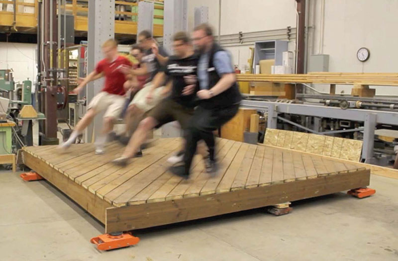
Figure 1: Impulse loading caused by occupants leaping/stopping in unison.
Test Methods
Standard test methods are not available for occupant-induced lateral loading, so two testing protocols were developed to represent worst-case conditions. Each person participating in the study was weighed, allowing occupant density evaluations of 10, 20, 30, and 40 psf. A conservative assumption was made that other than the attachment at the ledger, the deck substructure would provide negligible lateral resistance; therefore, the deck was supported on rollers as shown in Figures 1 and 2 (page 38). In reality, many decks have some degree of lateral support provided by stairs, braces or other configurations that provide resistance to lateral movement. Lateral stiffness of decks differs substantially when loaded parallel versus perpendicular to the ledger; hence, loadings in both directions were conducted for all cases.
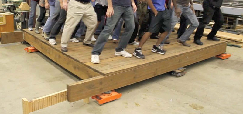
Figure 2: Cyclic loading caused by occupants swaying side-to-side in unison.
The first load case was an impulse. For this type of loading, the occupants were instructed to start at one end of the deck and run and jump, in unison, towards the opposite side of the deck. Impulse loading was conducted with an occupant density of 10 psf to allow occupants ample room to run and jump. The second load case was cyclic, in which the occupants were instructed to sway, in unison, following visual and audible cues, back and forth at an approximate frequency of 1 Hz.
All impulse and cyclic tests were performed with motion parallel and perpendicular to the deck ledger. Forces were recorded at the two corners where the deck was anchored to the laboratory floor with steel brackets (simulating the building). In an actual building, the load path would differ from this test set-up since deck ledger boards are typically connected to the house along the entire length. The rationale for attaching the deck at two discrete points was to obtain a conservative (high) load estimate by attracting all load to the two attachment points. Load path from the deck into the house floor diaphragm was investigated in a separate study reported in a paper by Parsons et al. (2013a).
Results & Discussion
Results of this study were reported as equivalent uniform lateral surface tractions in psf generated by occupant actions. These values were determined by dividing the total force generated by the surface area of the deck floor. Loads in this form can easily be applied to decks of any size for design purposes. For the perpendicular to ledger load cases, the total force was taken as the sum of the two load cells. For the parallel to ledger load cases, the total force was taken as two times the maximum load cell value by applying basic equilibrium principles.
Table 1: Forces generated by occupants from impulse loading.
Impulse Loading
Forces generated for both deck configurations are shown in Table 1 for the perpendicular and the parallel to ledger load cases. All tests were recorded with high-definition video and retained by the authors. A sample still shot from the video can be seen in Figure 1 for the impulse loading.
Perpendicular to ledger: Impulse loads were similar for both decking configurations since deck stiffness was primarily controlled by axial stiffness of the joists rather than the decking orientation. The stiffness of the deck resulted in many short duration pulses as each person landed, but was not flexible enough to allow the pulses to accumulate into one large force.
Parallel to ledger: When impulse loading was directed parallel to the deck ledger, as shown in Figure 1, decking orientation controlled the stiffness of the system. Table 1 shows that the less stiff deck (with decking oriented parallel to the ledger) experienced lower loads as the pulse duration was relatively long at impact, and the occupants velocities were reduced by the deck movement as the occupants pushed off to accelerate. The greatest loads were observed for diagonal decking. Apparently this scenario “hit the sweet spot” of a deck with just enough flexibility to allow the individual impacts to act additively in a long enough time interval. In any case, the maximum traction load of 9.4 psf was less than the value of 12.1 psf for cyclic loading.
Cyclic Loading
Figure 2 shows a sample still shot from the video for the cyclic side-sway motion.
Table 2: Forces generated by occupants from cyclic loading.
The highest lateral load observed in all tests was 12.1 psf, as shown in Table 2. In this case, deck boards were oriented parallel to the deck ledger, resulting in a very flexible deck that swayed back and forth approximately 7 inches each way at a frequency of approximately 1 Hz. These large displacements caused significant inertial forces from the mass of the deck and also allowed the occupants to “feel” the deck movement, making it easier for them to synchronize their movements. As displacements of the deck reached maximum values of approximately 7 inches, the occupants started pivoting their hips (like downhill skiers) with the deck while leaving their upper body nearly motionless. At this point, it could be argued that the majority of the force generated is coming from deck inertial forces rather than from the occupants. This would imply that if lateral sway/acceleration of a deck is adequately restrained, these inertial forces could be reduced or eliminated. For example, when the cyclic motion was perpendicular to the deck ledger (the stiffest orientation), the maximum traction load was 4.5 psf. In summary, it could be argued for design that 12 psf would provide a reasonable upper estimate of lateral loads from occupants for flexible decks.
Conclusions
When deck boards were oriented parallel to the ledger and occupant loading was applied parallel to the ledger, large side-to-side displacements were observed when a cyclic action was performed by the occupants. These large displacements produced significant inertial forces with a maximum equivalent uniform lateral surface traction load of 12.1 psf. When cyclic actions were perpendicular to the ledger (i.e. the stiffest lateral direction), it was difficult for the occupants to synchronize their movements and the resulting maximum uniform surface traction load was 4.5 psf. The maximum recorded impulse load resulted in a uniform lateral surface traction load of 9.4 psf as compared to 12.1 psf.
A design lateral load of 12 psf of plan area is recommended, which conservatively includes inertial forces from a flexible deck. The 12 psf observed in the laboratory is similar to the lateral load specified in Table 4-1, Footnote k (ASCE/SEI 7-2010) for reviewing stands, grandstands and bleachers, which call for 24 lb/linear feet of seating (assuming seats are 2 feet apart, the resulting load would also be 12 psf). One surprising outcome of this research is that measured lateral loads from occupancy exceeded the calculated worst-case lateral loads from wind or seismic events (Lyman and Bender, 2013; Lyman et al., 2013). Furthermore, extreme occupant loading can occur anywhere in the US, while extreme wind and seismic events are limited to smaller geographic regions.
The testing protocol and conclusions reported herein are based on the assumption that the proposed deck or porch sub-structure has no auxiliary lateral support to resist occupant loading. The design professional is encouraged to include lateral support structures to resist all or part of the lateral loads produced by occupant loads (as well as other design loads such as wind or seismic).
It should be noted that the weak link in the load path might be the fasteners used in the joist hangers. Test assemblies were fabricated with screws to prevent premature withdrawal of nails in the joist hangers. The first step in any lateral load analysis, when required, should be to address the lateral design capacity of the joist connections (hangers) as nails would likely not be adequate in resisting lateral loads produced by occupants.▪
Acknowledgement: Donation of construction hardware from Simpson Strong-Tie is gratefully acknowledged.
This article, which originally appeared in Wood Design Focus, contains minor edits and additions and is used with permission. Wood Design Focus is a quarterly publication available through the Forest Products Society at www.forestprod.org.
References
American Wood Council (AWC). 2010. Design for Code Acceptance 6: Prescriptive Residential Wood Deck Construction Guide. AWC, Leesburg, VA.
American Wood Council (AWC). 2008. Special Design Provisions for Wind and Seismic. ANSI/AF&PA SDPWS-2008, Washington, D.C.
American Society of Civil Engineers (ASCE). 2010. Minimum Design Loads for Buildings and Other Structures. ASCE/SEI 7-10, Reston, VA.
Homan, S.W., Boase, A.J., Raider, C.J., Jensen, H., Matthews H.W., Smith, G.B., and Wetzel, C.H. 1932. Horizontal forces produced by movements of the occupants of a grandstand. American Standards Association Bulletin 3(4).
ICC. 2009. International Building Code (IBC). http://publicecodes.cyberregs.com/icod/ibc/2009/index.htm
ICC. 2009. International Residential Code for One-and-Two Family Dwellings (IRC). http://publicecodes.cyberregs.com/icod/irc/2009/index.htm
Legacy Services. 2010. Outdoor deck and porch injury study. www.buildingonline.com/news/pdfs/Outdoor-Deck-and-Porch-Injury-Study.pdf
Lyman, G.H. and D.A. Bender. 2013. Wind load determination for residential decks. Wood Design Focus – A Journal of Contemporary Wood Engineering 23(2):3-8.
Lyman, G.H., D.A. Bender and J.D. Dolan. 2013. Seismic load determination for residential decks. Wood Design Focus – A Journal of Contemporary Wood Engineering 23(2):9-14.
Parsons, B.J., Bender, D.A., Dolan, J.D., Tichy, R.J., and Woeste, F.E. 2013a. Lateral load path and capacity of exterior decks. ASCE Practice Periodical on Structural Design and Construction (in press).
Parsons, B.J., Bender, D.A., Dolan, J.D., and Woeste, F.E. 2013b. Deck and porch floor lateral loading by occupants. ASCE Practice Periodical on Structural Design and Construction (in press).
Schutt, C.A. 2011. Improving deck safety. LBM Journal (May/June): 26-28.