
Evaluating the Seismic Performance of Concrete Elements
Seismic assessment of earthquake-damaged buildings typically involves damage surveys and structural analyses. In this unique project, the evaluations also included the seismic testing of nine full-scale beam-column connections and two portions of shear wall slab connections, extracted from reinforced concrete buildings with minor damage. The concrete specimens had to be tested in less than a year. As the number of specimens and limited time exceeded the capacity of available testing facilities, a local warehouse was turned into a temporary testing facility. With the lack of a strong floor and strong wall, the project team designed a self-equilibrating steel test frame so that the reaction forces transferred to the warehouse slab were minimized. The innovative test frame accommodated all the different specimens in earthquake-type cyclic tests while simulating the boundary conditions of the specimens inside the buildings.
Innovative Test Frame
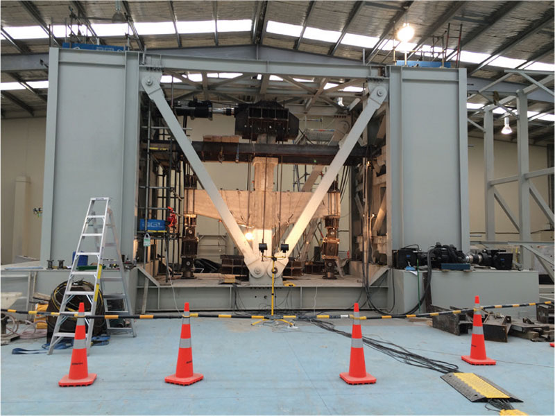
Figure 1. Self-reacting test frame.
The test frame, shown in Figure 1, consisted of two 20-foot-high steel towers separated by 20 feet and supported by 3-foot-thick steel-concrete (SC) composite footings resting on top of the warehouse slab. Horizontal steel diaphragms connected the two towers at the top and bottom. The top diaphragm was made removable to facilitate installation of the heavy specimens inside the frame. The bottom diaphragm was elevated from the floor so that the specimen reactions were transferred to the end towers without damaging the warehouse slab. Removable V-braces connected the bottom diaphragm to the two towers.
The test frame was designed under strict deflection requirements so as not to influence the accuracy of the test results. The maximum lateral and vertical deflection were limited to 1⁄8 inch and 1⁄16 inch (downwards), respectively, while no uplift was allowed. The efficient structural system of the frame provided the necessary lateral and vertical stiffness. The two end towers were comprised of Universal Column (UC) sections UC310 and UC200, which were braced at different levels and stiffened by 3⁄8-inch-thick steel plates. The middle tower columns, which supported the actuators, were welded-column (WC) sections WC400 and were perforated at various levels to enable adjustment of the actuator to match the different specimen heights. All tower columns were bolted to the SC footings, which consisted of steel boxes filled with 52 yards of high early-strength concrete, each, and reinforced with internal steel diaphragm plates. The SC footings sat on top of the warehouse slab and provided stability and limited vibration during testing.
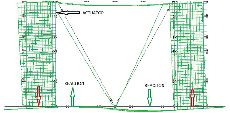
Figure 2. Test frame deflected shape under maximum actuator load.
The biggest challenge during the frame design was the low bearing capacity of the warehouse slab, estimated at 14.7 pounds per square inch (psi). The frame was designed to internally equilibrate the applied and reaction forces to overcome this limitation, as shown schematically in Figure 2. The actuator, at its maximum capacity, imposes up to 3,688 kip-feet applied moment at the base of the frame. This moment generates a force couple (shown in red in Figure 2) that applies a high bearing pressure underneath one tower and large uplift forces on the other tower. On the other hand, the specimen reaction forces (in green in Figure 2) generate a reaction moment which equilibrates the applied moment. This equilibrium of forces requires the middle platform to behave in flexure, similar to a strap footing. The middle platform was raised 2 inches from the warehouse slab to function as required. As the reaction forces along the middle platform act in the opposite direction to the applied vertical forces, the bearing pressure applied to the warehouse slab was gradually reduced, as shown in Figure 3 for the case of maximum applied actuator force of 450 kips. The SC footings uniformly spread the applied pressure on the warehouse slab, eliminating any localized stress concentration underneath the towers and ensured contact to the slab at all times (i.e., no uplift).
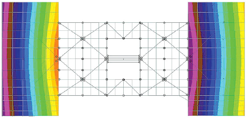
Figure 3. Contact pressure distribution under maximum actuator load.
The SC footings were connected by the 20-inch-thick middle platform which consisted of steel beams partially encased by a 16-inch concrete slab that reduced deflection and vibration during the seismic testing. The middle platform beam along the same axis of the actuator column was drilled with anchor points to enable the adjustment of the struts supporting the specimen beam ends. Each anchor point location was designed for an allowable vertical load of 340 kips in tension or compression, and for a maximum vertical deflection of 1⁄16 inch. The finite element analysis of the frame was carried out using STAAD Pro software (Figure 4).
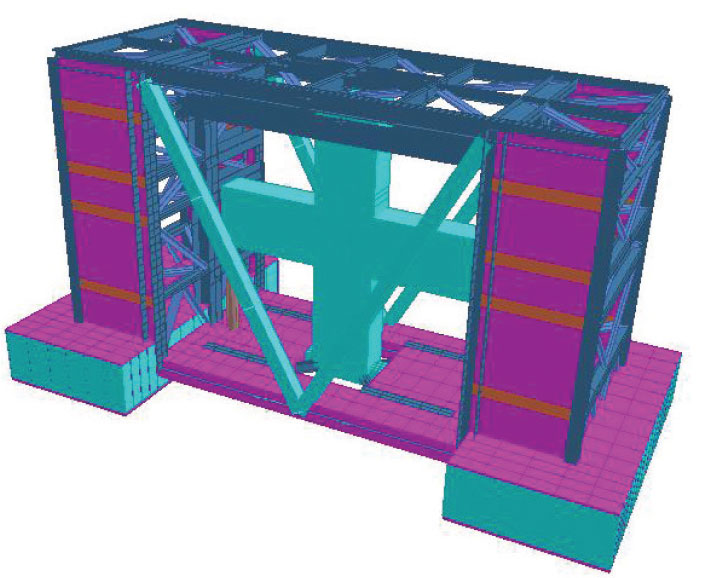
Figure 4. FE model of test frame with the largest specimen inside.
Because of the warehouse limitations in height and access, the test frame was designed and fabricated as four separate modules which were assembled at the site (Figure 5): the bottom platform including foundation boxes, the two towers, and the top platform. This design allows future transportation and reassembly at a different location.
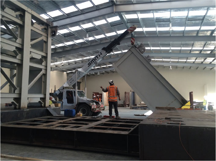
Figure 5. Assemblage of test frame in the warehouse.
Testing Process
Two 20-ton-capacity Franna cranes lifted and installed all the concrete specimens inside the test frame. Accurate synchronization of the crane movements was essential for proper lifting and movement of the heavy specimens, which were carefully braced before installation. Two 450-kip double-acting MTS hydraulic actuators applied the lateral forces at the top of the specimens, simulating the earthquake action (Figure 6).
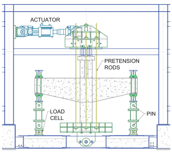
Figure 6. Specimen layout under cyclic testing.
For the beam-column connections, the loading represented seismic forces acting on the specimens as if they were inside the buildings. Secondary supports consisting of heavy steel caps at the bottom and top of the column, and double-pinned struts at the beam ends, forced the specimen to deflect as during a seismic event. In other words, a zero moment at the beam and column ends (pin connections) and free translation except at the column bottom, which is the reference point for relative displacement (Figure 6). The double-pinned struts consisted of 10- x 10-inch-square hollow sections with 80-millimeter-diameter pins attached at both ends. The bottom pin was bolted to a load cell used to measure the specimen reactions. Pretension rods attached the steel caps to the column, and the double-pinned struts to the beam ends. The axial forces in the pretension rods in the columns represented the gravity load carried by the column inside the building.
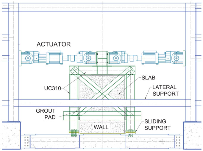
Figure 7. Slab-wall specimen in test frame.
The slab-wall specimens consisted of portions of a concrete shear wall with its tributary slab and were intended to test the shear transference at the slab-wall interface during a seismic event (i.e., shear friction). In this test configuration, the walls of the specimen were placed flat on the test frame floor while the slab stood upright (i.e., in the vertical position). A secondary frame consisting of UC310 sections with lateral bracing was designed to transfer the actuator force from the top to the lower part of the steel columns and then to the slab-wall interface via grout pads (Figure 7).
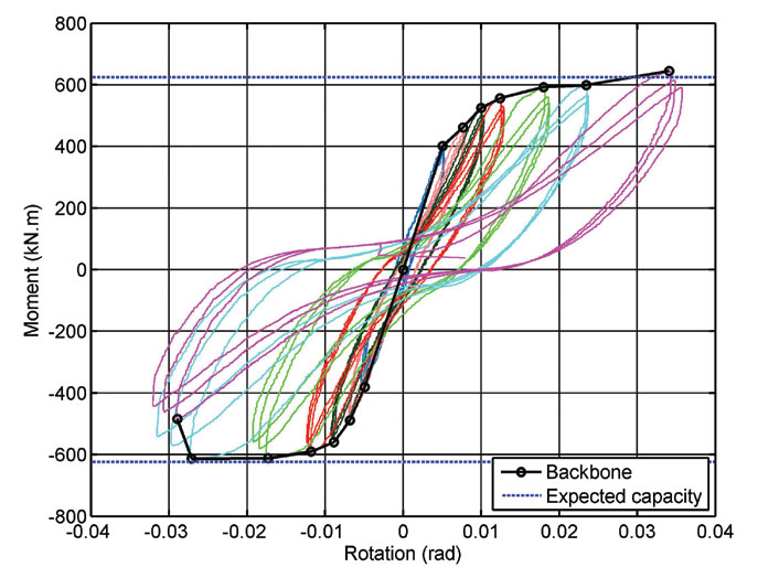
Figure 8a. Moment vs. rotation results.
The beam-column joint regions and slab-wall interfaces were externally instrumented with high accuracy string potentiometers to record beam and column flexural rotations and shear deformations. The specimens were subjected to quasi-static reversed cyclic loading in accordance with the American Concrete Institute (ACI) Committee 374.1. The loading consisted of the application of incremental displacements at the top of the specimens, up to a drift of 3% or failure of the specimen. After each cyclic loading, the test was stopped to identify and measure cracks and also take photographic records. The test results consisted of force versus deformation plots at critical sections of one of the specimens. Figure 8a shows the moment versus rotation plot at the beam-to-column section of the specimen, shown at different cycles. Figure 8b shows the damaged suffered at the beam-column joint after the last cycle. During the tests, the deformations at critical locations of the test frame were also recorded, being the maximum displacement around 1⁄16 inch at the top of the frame, which was only 1% percent of the maximum applied displacement (+/-5 inches) and thus considered negligible.
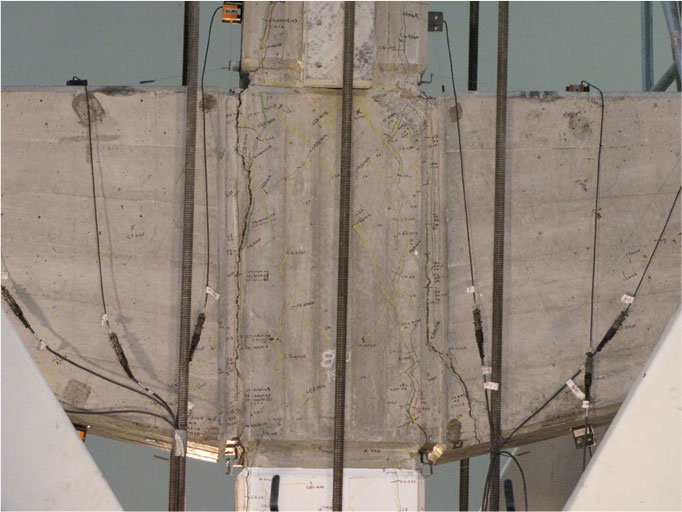
Figure 8b. Specimen damage after cyclic testing.
Conclusions
The temporary testing facility, equipped with a self-reacting steel test frame, proved to be a successful alternative to performing seismic testing of large concrete elements on time and within budget. The innovative self-reacting frame, which can be transported and re-assembled at a different location, eliminates the need for strong-floor and strong-wall, thus dramatically reducing costs. The test results provided valuable information to evaluate the buildings’ seismic performances.▪