
Among the most powerful innovations in recent years in the structural engineering profession is the widespread adaptation and use of nonlinear analysis methods for seismic issues. The concept of nonlinear behavior has been around for decades, but only recently – say, within the last 15 years – have practical analysis methods been introduced and embraced by many. Among these is the static pushover method, which enables a representation of nonlinear behavior without the need to develop and run sophisticated response history analyses.
Admittedly, the pushover procedure is not without its shortcomings – no analysis method is – but even such simplified methods can provide a useful glimpse of actual behaviors that could never be captured with traditional elastic analysis. In fact, they can expose the limitations of conventional analysis approaches, as well as the limitations of conventional structural assemblies and geometries long thought to be reliable.
Simple questions may sometimes haunt our experience and cause us to re-think designs and concepts that we once embraced uncritically. For example: What is the consequence of a brace buckling in compression? There are obvious local consequences in the structure that need no further elaboration here, but what about beyond the localized failure?
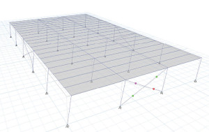
Figure 1. ‘X’ Braced Frame under transverse loading.
Consider the perfectly symmetrical braced frame structure shown in Figure 1. This three-bay by five-bay, one-story (12-foot high) building has columns spaced at 24feet in each direction. Brace sizes are typical, and are controlled by the limiting slenderness parameters found in AISC 341-10. This simplified model is the “big dumb box,” shunned by architects and embraced by engineers for a common reason, its regularity. By all conventional definitions, this structure is regular and symmetrical.
Indeed, lateral analyses using equivalent force methods demonstrate this to be the case, with perfectly uniform displacement under application of centered lateral load in the transverse direction. If the diaphragm is rigid, we know that we must accommodate a minimum of 5% accidental eccentricity. Doing this still yields a structure characterized as “regular,” since the peak drift is not greater than 1.2 times the average (ASCE 7 Table 12.3-1). The design thus appears sound; we need not do anything more to address potential torsional effects.
Next, consider the buckling question. Buckling can of course be characterized as a form of nonlinear behavior, but even more, a brace with the potential for buckling in compression and yielding in tension should also be characterized as potentially exhibiting hysteretically asymmetric nonlinear behavior – a complex way of saying that nonlinear behavior is different in tension vs. compression. There is nothing earth-shattering here. For the compression case, a buckled brace essentially loses its stiffness, and for the ‘X’ configuration the tensile brace then becomes the primary bracing element in the bay – at least until a load reversal occurs and the compression members and tension members switch roles.
What happens next? For perfectly balanced behavior, we should see simultaneous buckling of the brace on the opposite side of the building. However, the 5% accidental eccentricity alone is enough to cause the braces on one side of a building to buckle before those on the other side. For this scenario, nonlinear static analysis methods predict a peak diaphragm deflection equal to 1.24 times the average diaphragm deflection at the prescribed target displacement, thereby breaching the 1.2 threshold of a “regular” diaphragm.
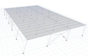
Figure 2. Chevron Braced Frame under transverse loading.
Consider also the altered bracing configuration (chevron) of Figure 2. For this case, a brace buckled in compression not only reduces the frame stiffness by about 50%, but also significantly reduces the counteracting resistance that would enable effective performance of the tensile brace. For this case, nonlinear analyses show that peak diaphragm displacements are 1.47 times the average displacement, well into a range that would qualify as an “Extreme Torsional Irregularity.”
This example is purely hypothetical, and the structure could certainly be designed using conventional procedures and not be tagged as extremely torsional. However, the simple nonlinear analysis methods clearly show that a potential for extreme torsion exists as a consequence of braces buckling. Another case where buckling of a brace might introduce an irregularity in an otherwise regular condition is a multi-story braced frame. As a brace buckles, frame stiffness could easily be reduced to the degree that vertical irregularities are introduced (ASCE 7 Table 12.3-2).
The potential irregularities mentioned previously stem from one phenomenon common to any conventionally braced system: nonlinear asymmetric hysteretic behavior. To a degree, this is accounted for by response modification factors with a lower magnitude than other systems demonstrating nonlinear symmetric hysteretic behavior. However, a diminished value of R does little to reduce the potential for irregular behavior.
So what are the other options? Simply put, the effects of nonlinear asymmetry can largely be overcome by other lateral systems, such as special moment frame, eccentric braced frame, and buckling restrained braced frame (BRBF). For other materials, similar symmetry of hysteretic behavior may be developed – e.g., concrete shear walls, concrete moment frames, and wood shear walls. Each of these systems has its advantages, the BRBF being particularly attractive because it captures the ductility of a moment frame without the limber consequences.
Whereas earlier codes commonly allowed the use of ordinary bracing systems, the code development and adoption process has gradually nudged such systems to the realm of Occupancy Category I, where there is low risk to human life in the event of failure. Currently, special concentric braced frames are the only conventional bracing system qualified for use in standard occupancies (or greater) in high seismic regions. What will future changes to the code include? Will the day come when conventional bracing systems are no longer deemed suitable for any occupancies?▪