
This article summarizes the development of a structural model to analyze and design a concrete masonry building that includes a structural steel roof and concrete mat foundation supported on concrete grade beams and drilled concrete piles (caissons). The building (Figure 1) will enclose large electrical equipment at a water treatment facility that is near a major seismic fault in northern California. The design was completed by the office of Carollo Engineers in Walnut Creek, California, and the author developed the model and conducted analyses using Bentley Systems STAADPro software.
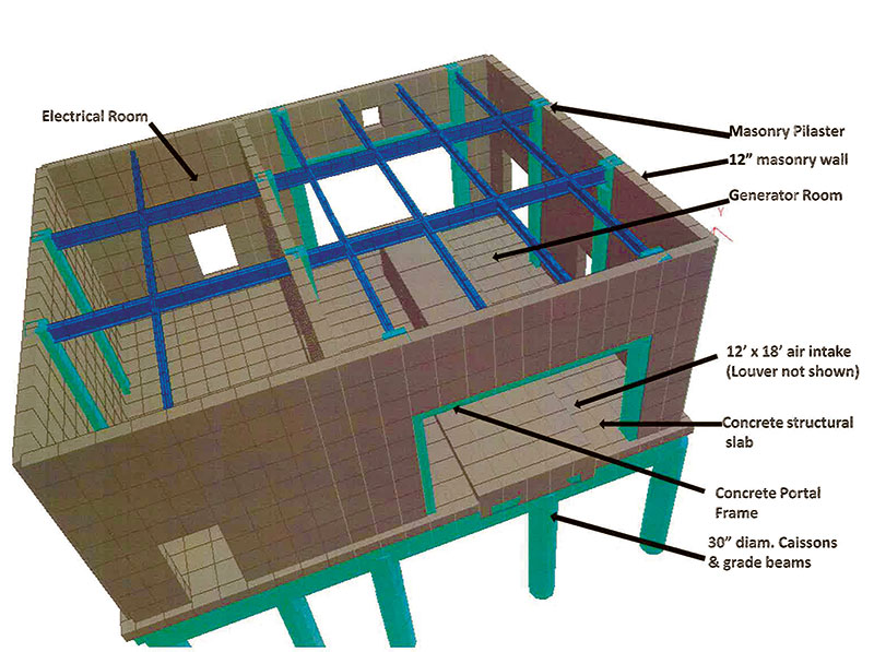
Figure 1: Structural rendering of generator building with roof deck removed.
Design Challenges
The project included seismic design considerations that, taken collectively, made modeling the otherwise unimposing Generator Building somewhat unusual, including:
- Proximity to the San Andreas Fault system in northern California;
- Large louvered openings in masonry shear walls for air intake and exhaust;
- Concrete caissons threaded in an unsymmetrical pattern between numerous existing buried utilities;
- A complex array of vertical and horizontal soil springs surrounding the mat foundation and concrete grade beams;
- Separate soil springs for caissons penetrating layers of disturbed soil and embedded in fractured shale;
- Latest code requirements for analysis of accidental torsion, amplified torsional effects, and orthogonal earthquake load combinations for rigid diaphragms;
- Substantial concern for accurate determination of seismic effects at steel beam to masonry wall connections that have limited ductility, under a multitude of load combinations.
Model Setup and Material Selection
The model setup was primarily accomplished using the software’s graphical user interface, occasionally in combination with the text editor. Roof deck, masonry walls and concrete mat were modeled as plates two feet square. Structural steel roof purlins and girders were assumed initially, and the program selected them during the final analysis based on AISC design parameters. Dimensions for masonry wall pilasters, concrete grade beams, and caissons were initially assumed as well. Concrete portal frames were placed around the large louvered openings in the east and west bearing walls. Building dimensions were frequently revised during the early design stages by other engineering disciplines. It was relatively easy to keep pace with these model changes by selecting the entire geometry for the affected portion of the structure and then moving it.
The author selected 1½-inch deep steel roof deck with 5¼-inch reinforced concrete topping and, based on experience, decided that the beam sizes would be relatively light and not of the magnitude that would economically justify activating the available beam/deck composite design tools. Instead, a concrete slab was assumed with material characteristics that allowed the model to replicate the stiffness and strength of the actual concrete-topped steel deck as specified on the design drawings. Three trials led to the selection of density, elastic modulus, shear modulus, and Poisson’s ratio for the concrete deck to replicate the diaphragm stiffness that was previously calculated using the flexibility factors documented in the International Code Council Evaluation Report for the deck.
Design codes specify that “cracked” masonry and concrete should be assumed in the seismic design. Based on ACI 318 Sect. 8.7 and ACI 530 Sect. 1.9 commentary, this requirement for reduced stiffness was achieved by reducing the moduli of elasticity and shear, and using the corresponding Poisson’s ratio. Masonry design codes report a broad range of values for these moduli, and mid-range values were selected for a fully grouted and reinforced wall with pilasters.
Geotechnical Requirements and Software Issues
The geotechnical consultant provided vertical capacities for the 30-inch-diameter caissons and indicated that the shafts would need to extend 8 feet to bedrock, and 5 to 10 feet into the fractured shale. Soil improvement was not feasible due to the multitude of existing buried utilities. The consultant provided stiffness values for horizontal and vertical “soil springs” for the mat, caissons, and grade beams, which were modeled initially as “compression only” springs.
During insertion of the horizontal springs at grade beams, it became apparent that these springs would override the vertical springs that had been previously assigned to the same nodes for the slab. With the assistance of Bentley Technical Support, the author determined that the springs could be reinstated by inserting the spring values in the text editor instead of the graphical interface. Bentley indicated that this anomaly would be resolved in the next release of the software.
The soil springs also resulted in a few “instability warnings” during initial analyses. Again with assistance from Bentley Technical Support, the author determined that these “warnings” could be eliminated if the “compression only” assignments were removed from support specifications prior to the primary load case listing, and re-inserted as “changed supports” in the text editor immediately prior to the list of load combinations.
Benefits of the Model
The structural model facilitated many aspects of the design process, including:
A. Heavy equipment is suspended from the roof beams, and seismic effects on the diaphragm could be accurately assessed (Figure 2).
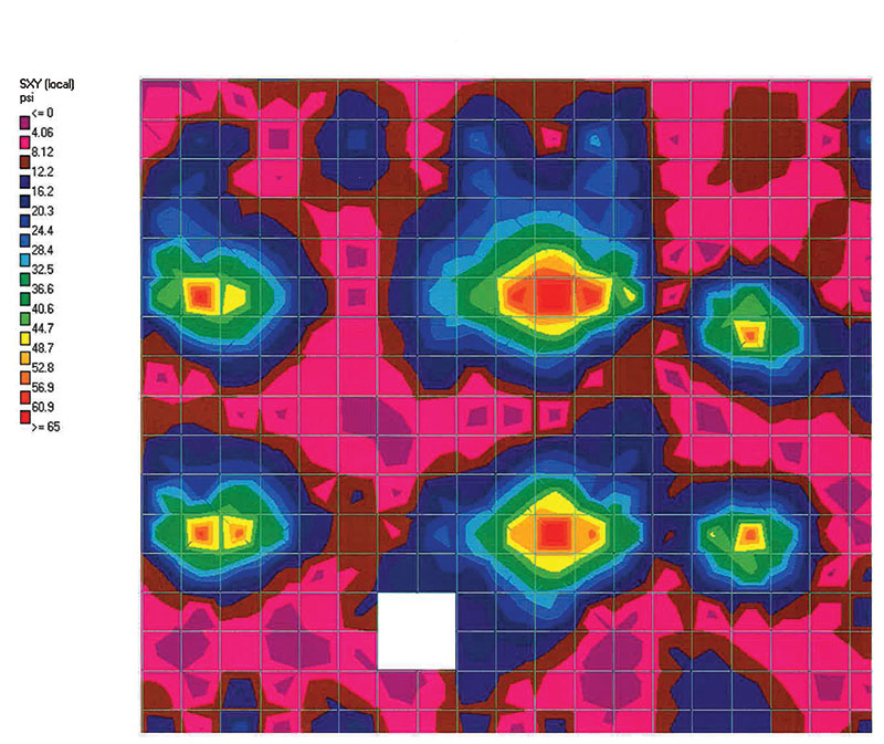
Figure 2: Maximum roof diaphragm shear in north-south direction.
B. The code required measurement of drift in multiple locations. Model analysis made it possible to quantify values at any location under all load cases.
C. It was not difficult to measure stresses around large openings in shear walls (Figure 3)
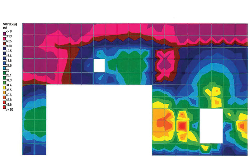
Figure 3: West wall maximum north-south seismic shear.
D. Precise stress patterns in the software’s post-processor enhanced economical placement of reinforcing (Figure 4).
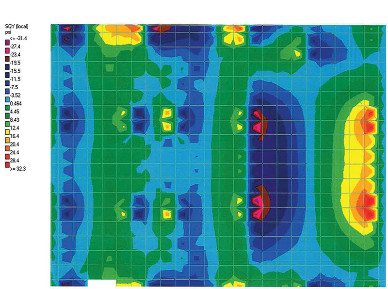
Figure 4: Maximum shear stress in ground floor slab.
E. It was possible to evaluate reactions for caissons under any load combination, and confirm adequate resistance to lateral loads and uplift.
F. Post-processing confirmed that masonry “breakout” stresses at steel beam and strut connections were within allowable values. Slip connections were provided where wall restraint would otherwise be inadequate.
Seismic Permutations
Model analysis enabled the project design to meet the relatively complex seismic requirements of ASCE 7-05 and the California Building Code. Accurate analysis of the caissons between existing utilities presented a unique challenge because the caissons were shallow and non-symmetrically placed. Also, reliable assessment of potential uplift and horizontal soil support was mandatory. To address this challenge, the author used the system of “Seismic Permutations” documented in the STAADPro technical reference documents.
More than 40 load cases were employed to assess torsional and extreme torsional irregularity; implement code requirements for redundancy, accidental eccentricities, and amplified torsional effects; and combine effects orthogonally. For the Generator Building, the task became easier when permutations were copied from a template that had been developed, improved, and updated iteratively during prior projects; pasted in the new project’s text editor; and re-factored for the requirements of the new structure. For example, model analyses concluded that torsional irregularity did not exist in the X-direction, but did exist in the Z-direction, and accidental loading in that direction also had to be amplified. Extreme torsional irregularity was shown to be non- existent in either direction. Code requirements also dictated that a redundancy factor of 1.3 had to be applied for load combinations in the Z-direction.
Conclusion
Understandably, some structural engineers could argue that the time spent in setting up a computer model is not always justified, nor is precise analysis always required. However, on many projects, time spent on this task – especially after reusable templates have been developed on prior projects – could amount to less time than would be spent using conventional spreadsheets, and final results could provide the project owner with greater value. Nevertheless, many initial templates can be like “black boxes” and checking with conventional spreadsheets (as done on this project) is essential.
The population in the South San Francisco area will rely on the Generator Building and its equipment to provide power and water during earthquakes that are not uncommon to the region. Modeling and analysis provided assurance that the source of this service will be sustained, even in the event of an extreme emergency. Comparable modeling efforts may be indispensable as seismic requirements and design codes continue to grow in magnitude and complexity.▪