
Concentrically braced frames (CBFs) resist large lateral forces due to wind and earthquake loading, and their ductility is largely derived from tension yielding and compressive buckling of the braces. Since 1990, AISC has focused on improving seismic resistance of CBFs by introducing detailing requirements for the connection, geometric limits of the brace, and capacity-design-type strength requirements for the gusset plate and the framing members.
In 1997, a requirement was introduced that the strength of the beam in a frame with braces in a chevron configuration must be able to withstand the post-brace buckling unbalanced forces, based on the assumption that the braces in tension yield and the braces in compression resist 30% of their critical buckling loads (AISC 2010). However, many braced frames built prior to the mid-1990s do not meet this requirement and therefore are generally considered to be “weak” and substandard. A research project to address the performance and potential retrofit of these older braced frames is currently in progress.
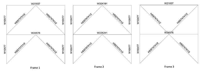
Figure 1a. Frames From Prior Work
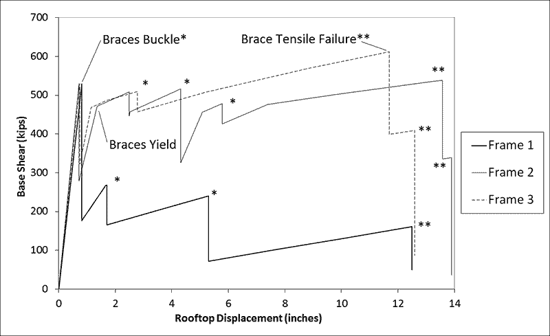
Figure 1b. Pushover Curves from Prior Work.
The article How Big is that Beam? (STRUCTURE magazine, November 2014) addresses this beam strength issue. The author analyzed three two-story frames using a nonlinear pushover analysis, shown in Figure 1a. The analyzed frames included a weak-beam chevron braced frame (Frame 1), a strong-beam chevron braced frame (Frame 2), and a multi-story X-braced frame (Frame 3); the results are repeated in this article as Figure 1b. Frames 2 and 3 were found to perform adequately, but Frame 1 exhibited a significant loss in strength and stiffness after brace buckling. As seen in the Figures, the predicted response of each braced frame system is characterized by sudden drops in strength, which is not characteristic of braced frame tests with adequate connections. The 2014 article thereby concludes that a frame with an undersized beam results in poor frame performance. Further, the analysis suggested that Frame 2, with a strong beam and HSS braces meeting current AISC SCBF slenderness limits, may achieve an inelastic deformation of about 12 times the buckling deformation. The author did not provide dimensions for the frames reproduced in Figure 1a, but assuming a story height of 12 feet, this deformation corresponds to 4.0% to 4.8% average story drift. This assumed story height aligns with dimensions common in practice and corresponds to approximately 0.3% average story drift at brace buckling, which is typical of braced frames in experiments. While the observations from these analyses are logical based on the results presented, this article contends those results are dependent on numerous assumptions that mischaracterize CBFs. The consequences of these assumptions are clear in the experimental results described below, which vary drastically from the results in the previous work.
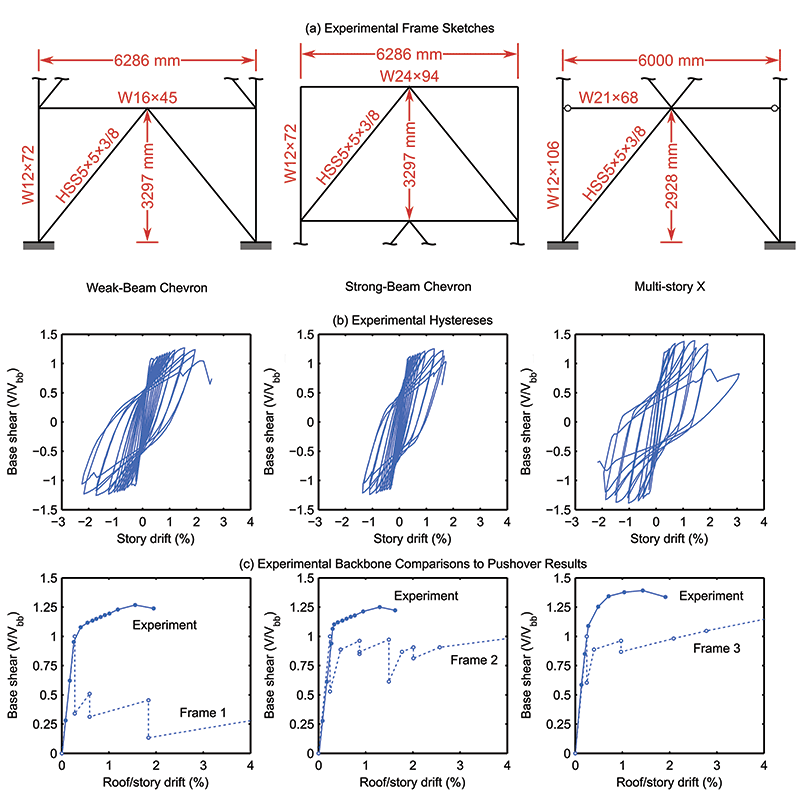
Figure 2. Comparison of Weak-Beam Chevron, Strong-Beam Chevron, and Multi-Story X Frames.
The authors have conducted tests that reflect the three categories of braced frames considered in the November article, and these experiments are discussed here. These tested frames include a chevron braced frame with a weak beam (left column of Figure 2), a chevron braced frame with a strong beam (center column of Figure 2; Sen 2014), and a multi-story X-braced frame (right column of Figure 2; Lumpkin 2009). Figures 2b and 2c present the experimental cyclic and backbone curves of the three frames. The braces in all three frames were identical (HSS5×5×3/8). While the member sizes of these frames are different than those shown in Figure 1, the relative strengths of the various members are similar. The frames were loaded quasistatically under a fully reversed increasing amplitude cyclic protocol. The base shear is normalized by the base shear force corresponding to buckling, Vbb. Equation 1 shows Vbb as a function of the buckling capacity of the brace, Pcr, and the brace angle, θ.
Vbb = 2Pcr cos θ Equation 1
The curves in Figure 2b show that there was little difference in the strength and stiffness of the weak- and strong-beam chevron frames. This is not intuitive, because the first story braces did not yield in tension while the second story braces did. However, frame action provided more lateral resistance on the first story than the second story. The chevron braced frame is an indeterminate system. While the truss assumption is suitable for initial design, it is not valid for seismic evaluation due to the complex inelastic behavior of CBFs. System capacity is dependent on the plastic mechanism, which is incomplete in models that neglect beam-to-column connection resistance and consequently lateral resistance due to frame action. This modeling simplification is pronounced in a weak-beam frame, where the plastic mechanism is yielding of the beam and buckling of the brace. For a strong-beam frame, the plastic mechanism is yielding of the brace in tension and buckling of the brace. Compared to the multi-story X-braced frame, the ultimate strengths of the chevron braced frames were lower, although the multi-story X frame had heavier columns, so some additional strength would be expected.
Another significant point of comparison is that the weak-beam chevron frame had approximately the same deformation capacity as the multi-story X frame prior to brace fracture. Deformation capacity is discussed in terms of drift range here, because local cupping deformation at the brace mid-span in compression typically precipitates fracture of the brace in tension; hence, both directions of loading influence the ultimate response. The weak-beam chevron frame reached a story drift range of 4.12% prior to brace fracture; this is comparable to the maximum story drift range of the multi-story X-braced frame, which was 4.38%. Thus, the weak beam did not impact system drift capacity significantly. Finally, it must be noted that none of the HSS braces achieved the large story drifts predicted for Frames 1 and 2 in the prior work. HSS braces of this slenderness fracture at maximum story drifts in the order of 2.5%, with a maximum drift range of 4.5% to 5%. This has been documented in hundreds of prior tests (e.g., Tremblay 2002 and Fell et al. 2009). Other brace cross sections, such as wide flanges, may achieve larger drift levels, but 4.0% average story drifts in tension are not achieved with HSS braces subjected to cyclic loading, as in earthquakes, since this implies much larger drift range (e.g., 8.0% if demand is balanced). Pushover analysis fails to capture the cyclic deterioration of the brace and is therefore unsuitable for predicting the deformation capacity of the system.
A number of factors likely contribute to the discrepancies observed between the pushover analysis presented in the prior work and the experimental results described here. Braced frames are commonly modeled as trusses, but it is clear from the test results that considerable resistance is derived from moments and shear forces that develop in the beams and columns. Also, while neither the monotonic nor cyclic protocols represent real earthquake deformation demands, cyclic protocols simulate the load reversals that an earthquake may induce in a structure. This enables phenomena such as strain hardening and low-cycle fatigue to occur, which are important response characteristics. Finally, springs or concentrated hinges that are used in some nonlinear structural analysis software may not be suitable for capturing the material and geometric nonlinearities that develop in braced frames; fiber-based or shell elements are required. Numerical results should always be interpreted with caution, and the limitations of software and input parameters (e.g., plastic hinge definitions) should not be overlooked.
Much research still needs to be conducted to determine the viability of weak beams in older and modern chevron braced frames, but these preliminary results suggest that good performance may be achieved using shallower, lighter beams than permitted by the current Seismic Provisions. This is in stark contrast to the results of simplified analyses of the How Big is That Beam? article, but the actual post-buckling behavior of braced frames is complex and difficult to capture without employing more robust analysis techniques.▪
Acknowledgements
This material is based upon work supported by the National Science Foundation Network for Earthquake Engineering Simulation under Grant No. CMMI-1208002, Collaborative Developments for Seismic Rehabilitation of Vulnerable Braced Frames and Graduate Research Fellowship under Grant No. DGE-1256082. Any opinion, findings, and conclusions or recommendations expressed in this material are those of the authors and do not necessarily reflect the views of the National Science Foundation. Additional support was also provided by the American Institute of Steel Construction in the form of steel donations.
References
AISC (2010). “Seismic provisions for structural steel buildings.” ANSI/AISC 341-10, American Institute of Steel Construction, Chicago, IL.
Fell, B. V., Kanvinde, A. M., Deierlein, G. G., and Myers, A. T. (2009). “Experimental investigation of inelastic cyclic buckling and fracture of steel braces.” Journal of Structural Engineering, 135(1), 19-32.
Lumpkin, E. J. (2009). “Enhanced seismic performance of multi-story special concentrically brace frames using a balanced design procedure.” M.S. thesis, University of Washington, Seattle.
Sen, A. D. (2014). “Seismic performance of chevron concentrically braced frames with weak beams.” M.S. thesis, University of Washington, Seattle.
Tremblay, R. (2002). “Inelastic seismic response of steel bracing members.” Journal of Constructional Steel Research, 58, 665-701.