
Accelerated Bridge Construction for Long Lasting Repairs on Aging Highways
“Get in, get out, and stay out” governs the objectives of designing a repair and rehabilitation project on an existing highway facility. Such projects on aging highways need be done as quickly as possible and be long lasting so as to minimize disruptions to a local economy’s infrastructure.
Interstate 280 is a major corridor facilitating traffic in and out of downtown San Francisco. Caltrans maintenance engineers observed the gradual disintegration of hinges on the Southern Freeway Viaduct, a conventionally reinforced box girder bridge built in 1964 and located at the north end of I-280 in the Bay View and Dog Patch Districts of San Francisco. These hinges are located at the overlap of two frames, each consisting of multiple spans supported continually on columns 30 to 50 feet tall. One frame ends with a “seat” while the next frame is supported on the seat, thus forming a joint to allow for primarily thermal movement. Hinges are located at the transition of a negative moment into a positive one. The seat-side superstructure of a span has a negative moment due to the weight of the support-side superstructure adding a reaction force on the nearest bent. The reaction force on the furthest bent is reduced due to support on the seat, which also results in creating the positive moment on the supported side of the hinge. Theoretically this is depicted by classical statically indeterminate free-body diagrams for a beam with intermediate supports.
Rehabilitation work began after constructing temporary supports on both sides of the hinge and closing down this section of viaduct. The existing hinge and 25 to 30 feet of structural box girders of this 53-foot wide bridge were demolished and reconstructed to current Caltrans seismic standards. Removal and replacement included barrier rail and joint seal. The quantity of concrete removed and replaced was approximately 120 cubic yards per hinge. Four hinges and adjacent box girders were reconstructed over 3 holiday weekends. Each weekend consisted of a work window of approximately 100 straight hours, requiring careful planning. Scheduling, logistics, quality control measures, inspections, and selection of materials were paramount to success. Concrete design, mixing, batching and placement technique played no small role.
Project Description
As I-280 is vital to a major urban infrastructure, two approaches to construction of the rehabilitation project were considered. The first was staging partial construction of each hinge where at least a portion of the bridge could be available for traffic during construction. The estimate to do the original 3 hinges earmarked with this kind of staged construction was 140 working days. Working 7 days a week with no weather delays, this would have resulted in inhibiting traffic flow continuously for almost 5 months. When a 4th hinge was slated for replacement, the result would have been over 6 months of traffic inconvenience. Partial construction would also have involved potentially more serious consequences, such as traffic accidents or the hindrance of emergency response vehicles. Additionally, there is a constant risk imposed on construction workers by the proximity of moving traffic. The second construction approach considered was to completely close a portion of the viaduct and do an entire hinge during consecutive shifts, adding up to approximately 100 hours. It was determined viable to close the viaduct for these 100 hour periods and, to minimize commuter disruption, the work was scheduled around three separate 3-day holiday weekends (2014 Memorial Day, 4th of July, and Labor Day). For each of the closures, work commenced on the day preceding the weekend and finished in the early morning hours of the day immediately following the weekend. Two hinges were done during the Labor Day weekend. Three hinges are on the northbound structure while one is on the southbound structure.
The 1964 seat and support were 6 inches long across the width of the bridge, while the current seismic standard for hinges in box girder bridges is a minimum of 2 feet long. The 3-mile twin viaduct has hinges approximately every 300 feet. In 1995, the 6-inch seats were retrofitted with bolsters or diaphragms and hinge pipe beams that would provide support if the joint moved more than 6 inches in an earthquake. This was part of the retrofit program following the 1989 Loma Prieta earthquake; the program included enlarging footings and adding steel column casings. Some retrofitted hinges showed signs of distress over the years. Three northbound hinges and one southbound hinge continued deteriorating until it was deemed they were approaching failure, as spalling concrete had to be caught in nets to prevent injury or property damage below.
Removal
To facilitate isolated demolition/removal of the existing structure, temporary supports were required on both sides of the hinge. On the support side of the hinge, the temporary support was designed to carry the dead load of that span (900 kips). On the adjacent span of the hinge, the temporary support was designed to prevent mid-span deflection and column rotation after the seat was unloaded (800 kips).
The demolition was performed from the deck and had to be done very carefully and strategically so as not to damage the existing structure that was to remain, including exposed longitudinal reinforcement. Enough existing longitudinal reinforcement needed to remain intact for mechanical staggered splicing to the new construction. The demolition equipment was limited to 1200 ft-lb hydraulic hammers. A CUT Multi Crusher was used to crush and shear through stems (Figure 1). The final removal was hand labor using primarily rivet busters to prevent damage to the portion of the bridge that was to remain. To maintain a clean construction joint, a 1-inch saw cut was made on the entire exterior and interior surface of the superstructure along the construction joint. The entire demolition had a duration of approximately 16 hours.
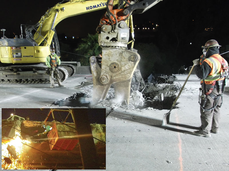
Figure 1. Tailgating into barrier forms.
Replacement
After demolition, falsework stringers were erected followed by installation of soffit and stem forms. Some of the existing rebar that was to be spliced did not match contract drawings based on archived “As-Built” drawings. Anticipating this, extra reinforcement of all sizes and extra mechanical couplers were brought on site along with a mechanical reinforcement bending table (Figure 2). Reinforcement cages for the hinge diaphragms were prefabricated (Figure 3). During the demolition and reconstruction, the structure was monitored/surveyed continuously at multiple locations for any lateral or vertical movement. Adjustments were made as necessary during demolition and prior to concrete placement.
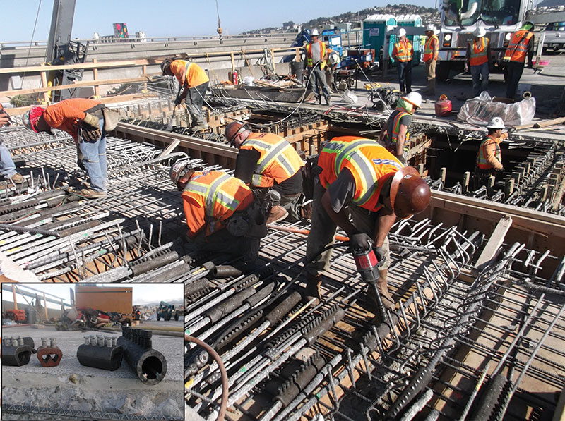
Figure 2. The couplers to mechanically splice the old to the new rebar.
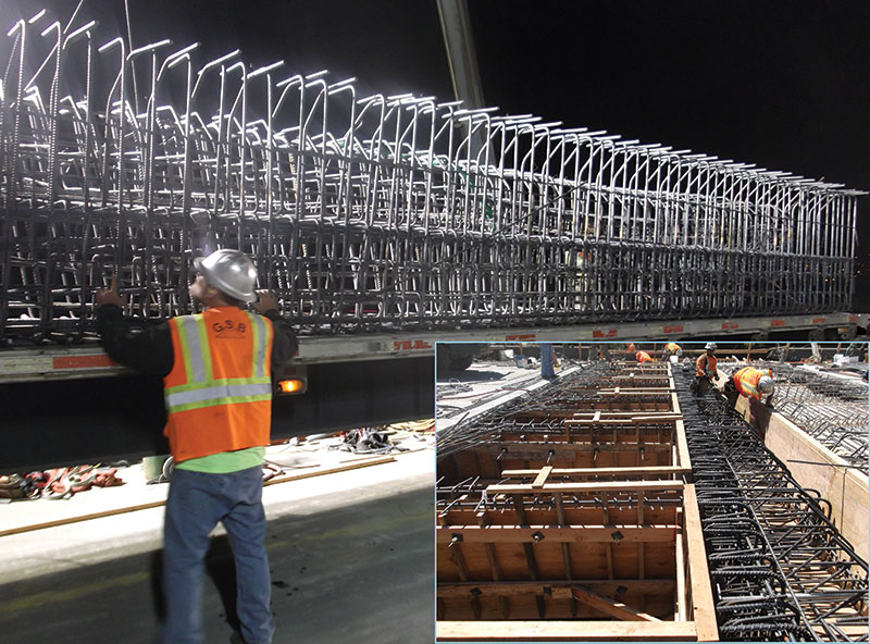
Figure 3. A prefabricated rebar cage for the hinge diaphragm.
Concrete
Each hinge reconstruction consisted of four pours: stem and soffit on the seat side, stem and soffit on the support side, deck pour seat side and finally deck pour supported side. Barriers and joint seals were the last order of work, notwithstanding clean-up and traffic markings.
Six weeks prior to Memorial Day, the contractor constructed a mock-up consisting of several stems and soffits and a portion of the hinge seat diaphragm. The mock-up was located on the ground in the concrete company’s yard in Sacramento. Batching and mixing was done by a volumetric mobile concrete truck complying with Caltrans’ Standard Specifications. To simulate the actual procedure, the truck was stationed next to a concrete pump and discharged concrete into the pump truck’s hopper. Since each placement sequence required more than the capacity of a truck, the concrete materials were replenished during placement as was the plan for the job site. Aggregates were continually loaded into the truck’s bins with skip loaders while the truck’s cement hopper was replenished using pre-packaged 1 ton super-bags lifted by crane. A water truck was used to keep water in the water tanks. A truck could hold about 10 cubic yards so the mock-up was to be more than one cycle, and thus the 16 cubic yard mock-up was deemed appropriate. Also, the largest element was a hinge diaphragm. To ensure compliance with Caltrans’ Mass Concrete requirement that a concrete element does not exceed 160 degrees F, the hinge diaphragm mock-up temperature was monitored. Peak temperature was well under 160 degrees F, thus no additional precautions were required. The truck and 2 back-up trucks were certified during the mock-up.
At the bridge site, aggregate stock piles were located on the deck spread out over several bents. Note concrete technology evolved to using the absolute volume method for batching concrete to address the bulking characteristic of aggregate with its changing volume with changing moisture content. Absolute volume practice uses weight to batch ingredients to address effects of bulking due to moisture. The stock piles were covered with plastic sheeting to maintain a near constant moisture content, particularly the sand stock piles, mitigating bulking characteristics and allowing for more accurate batching by volume. Cement super-bags were stored under the bridge. Continuous metering displaying volume per time of the ingredients and automatic dispatching tickets were required. Unit weights on samples taken during placement were used as a check on proportioning. Figure 4 shows how consistent the unit weight was throughout the entire project. The lowest unit weight correlated with the initial higher slump during the very first placement before water was slightly adjusted to achieve the desired 5- to 7-inch slump for placement.
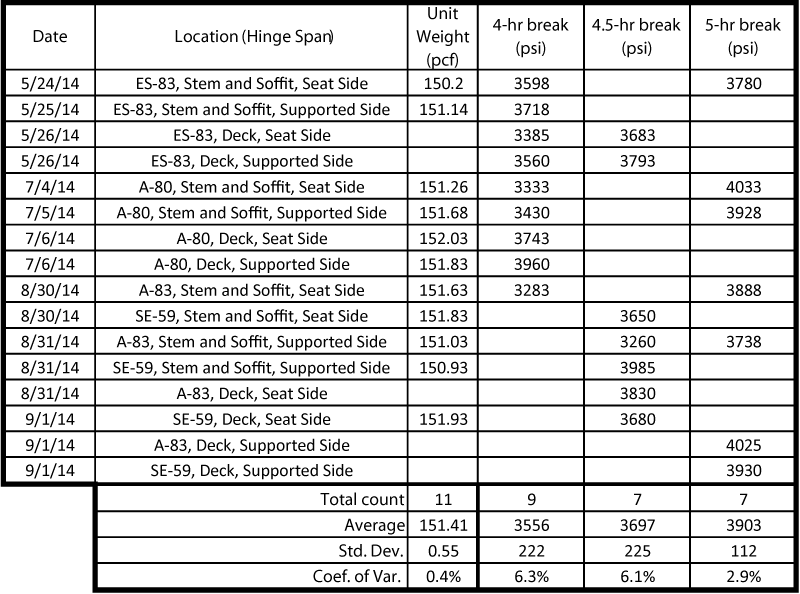
Figure 4. Unit weights and early strength.
The structural concrete design complied with 2010 Caltrans’ Standard Specifications for Rapid Strength Concrete. This material’s specification is based on the award winning I-10 Pomona Freeway project specifications constructed in 1999. Approximately 2 lane-miles of the 8 lane mile project on a heavily traveled portion of the I-10 was replaced during a 55 hour weekend window, with the remaining 6 lane miles completed during nighttime closures over a period of several months. The specification allows for any fast-setting cement meeting ASTM c219 for hydraulic cement. If other than a Portland cement is used, then some additional requirements are listed to ensure long-term durability. The contractor chose a calcium-sulfoaluminate cement as the fast-setting hydraulic cement ingredient, which happened to be manufactured by the same company providing the cement on the Pomona project.
The contractor was able to control the mix with admixture adjustment as the temperature varied and as the placement needs varied. There was no dead time waiting for strengths. The working time was engineered to be about an hour, so by the time the top of a stem was finished, the soffits achieved final set. The contractor’s crews were openly impressed has to how soon forms could be stripped so as to move on to the next operation. The last concrete placement was the barrier rail placement. Because it could be tailgated and a shorter working time could be easily accommodated by the nature of the element, that mix was engineered to produce 1 hour compressive strength of 2,000 psi on cylinders heated to approximately match the actual in-place temperature of the barrier concrete.
Cylinder break data are also shown in Figure 4. The cylinder breaks had coefficients of variation falling within the standard of concrete control range category of “very good” as classified by the American Concrete Institute per ACI 214 R-02. This coefficient of variation demonstrated consistent batching and mixing, and consistent properties of cement, aggregate and admixtures, thus achieving the high degree of quality control confirmed by quality assurance results. Figure 5 shows the strength gain with time up to 3 months.
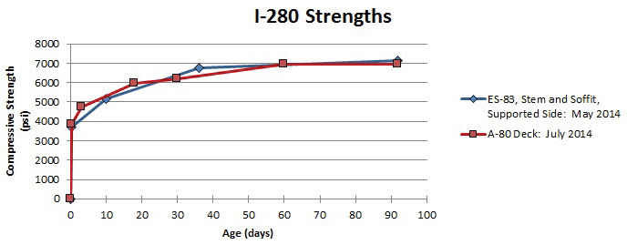
Figure 5. Compressive strength vs. time.
Conclusion
All the preliminary planning and diligence of the contractor, the mock-up, calibration of the mixer trucks, unit weight sampling taken during placement confirming proper mix proportions, the required care taken on the aggregate stock piles to ensure uniformity, standard QA sampling and testing, and the attention to detail during design and construction, resulted in achieving the objectives of this rehabilitation project.▪
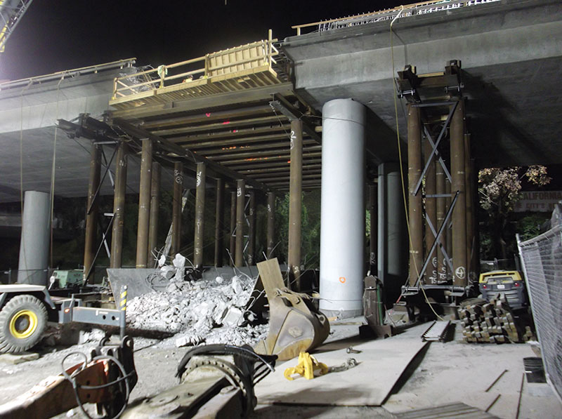
Figure 6. A view of a removed hinge and box from below.
Project Team
Owner: Caltrans
Construction Contractor: Golden State Bridge Inc.
Concrete Supplier: Precision Concrete Materials LLC
Fast Setting Cement Supplier: CTS Manufacturing Corp.