
Buro Happold Consulting Engineers, PC was an Outstanding Award Winner for the Crystal Bridges Museum of American Art project in the 2012 NCSEA Annual Excellence in Structural Engineering awards program (Category – New Buildings over $100 Million)
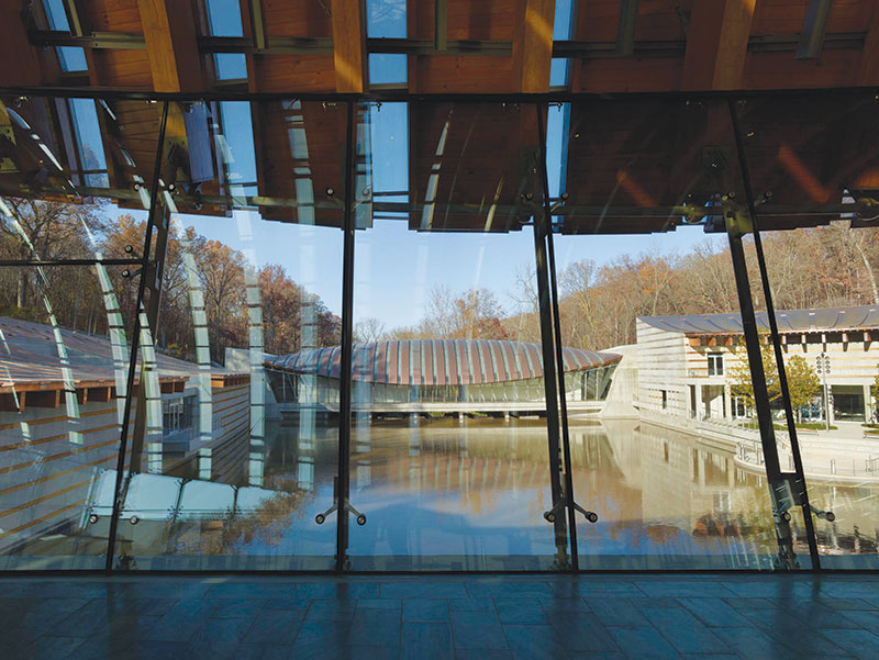
View from dining bridge across upper pond. Courtesy of Timothy Hursley
Crystal Bridges Museum of Art is an iconic museum inspired by the local Arkansas landscape and the exotic suspension bridges of Bhutan. The 201,000-square foot museum is a complex of eight buildings located in Bentonville, Arkansas. Designed by Safdie Architects, each of the eight buildings, although individually unique, relate to each other through a unified palette of concrete, wood, copper and glass. There are five “land” structures that nestle into the hillsides and three “water” structures that create a circular promenade on the site.
The land buildings are set in the sloped hillsides of the creek ravine. Where there is only soil under the buildings, drilled piers provide vertical support. Lateral loads are taken back through floor diaphragms and distributed to grade beam-supported minipiles farther up the slope that are inserted into rock sound limestone. The sizes of the grade beams are typically 30 feet deep with widths varying from 30 to 64 inches to accommodate the minipile geometries. The drilled pier diameters range from 2 to 3.5 feet, with rock embedment depths of 3 to 18 feet. The reinforcement included number 8 bar reinforcements with number 4 spiral ties.
The lower levels of the land buildings are concrete frames that feature either beams or flat slabs that span 20 to 30 feet and are column supported. The upper-level columns and retaining walls are spanned by curved laminated timber beams (glulams), 10.5 x 31 inches in cross section. The building roofs are made of locally sourced glulam beams with alternating strips of copper cladding and glazed skylights.
The bridge buildings notable because of their hanging arch forms, represented a real engineering challenge. Their bases form concrete weir structures that serve as the floors and, in the case of the two spanning buildings, also control the streamflow to create the signature museum ponds.
The roofs of these buildings are a series of non-repeating glulam arches, each of which has a unique inner and outer radius. Each arch is broken into three segments and tapers at the ends, varying in cross section from 10 x 32 inches to 10 x 24 inches. These arches rest on pairs of 4-inch diameter stainless steel cables strung between heavy concrete abutments that support the roofs. The roofs and floors are connected by external steel facade mullions that both support the facades and impart additional stability to the roofs under live loads.
The glulams are connected to each other by a series of T-shaped steel purlins, 5 x15 inches in cross section, located atop the glulam beams. Since the number of purlins is constant throughout the cross section, as the bridge roofs become wider, the spacing between the purlins gradually changes. This provides the T-shaped purlins with both a vertical and a horizontal inclination with respect to the glulams. The engineers also used smaller, secondary timber purlins to divide the roof into opaque and skylighted areas. These secondary purlins have ¾-inch cross bracing that provides the roof plane with a structural diaphragm.
The roofs are based on catenary shapes that are created by the deflection of the cables. The structures are designed so that the cables carry all of the dead load. Once the dead loads of the roofs were installed, the cables deflected and attained their final geometries. The facade mullions were then added, connecting the glulam beams directly to the ground. This created stiffer load paths that carried any additional live loads from the roofs. The mullions supplement the horizontal diaphragm of the roofs and provide lateral stability under wind and seismic loading.
The bridges are suspended from abutments at either end; these abutments rest on mat foundations that utilize shear keys and are located directly on rock. Rock anchors were installed along the rear portions of the abutments and sleeved through the abutments. Once the concrete for the abutments was placed, the anchors were pretensioned in order to resist the cable pull loads. The foundations of the peninsula-like Great Hall building are slightly different in that there is only one abutment. The cable structure is tied to rock anchors inserted into the pond for added stability.
The design of typical and repeatable details that could effectively be used with the complex geometry of the roof was one of the principal challenges of this project. One of these is the visible connection between the cables and the glulams at the typical ball joint castings. The detail functioned as a universal joint within the degree of movement defined by the geometry of the Great Hall, which presented the most challenging conditions of all of the bridge buildings. The repeatable detail could accommodate the number of variations that would occur as each glulam advanced along the cable.
Crystal Bridges, with its complex geometries, would not have been possible were it not for a high level of collaboration between the design team, contactors, and the owner, and the use of BIM and digital fabrication technologies in order to ensure that the complex geometries specified could be designed and built.▪