The Wood Frame Construction Manual (WFCM) for One- and Two-Family Dwellings was updated and is designated ANSI/AWC WFCM-2012 (Figure 1). The 2012 WFCM was developed by the American Wood Council’s (AWC) Wood Design Standards Committee and is referenced in the 2012 International Residential Code (IRC) and 2012 International Building Code (IBC).
The WFCM includes design and construction provisions for high wind, seismic, and snow loads for connections, wall systems, floor systems, and roof systems. A range of structural elements are covered, including sawn lumber, structural glued laminated timber, wood structural sheathing, I-joists, and trusses.
Primary changes to the 2012 WFCM are listed here, and are subsequently covered in more detail:
- Design load provisions are updated per ASCE/SEI 7-10 Minimum Design Loads for Buildings and Other Structures
- Wood structural panels are permitted to resist wind uplift
- Shear wall story offset provisions are clarified
- Design values for lumber, structural glued laminated timber, and fasteners are in accordance with the 2012 National Design Specification® (NDS®) for Wood Construction and 2012 NDS Supplement: Design Values for Wood Construction
- Engineering design of horizontal diaphragm assemblies and vertical wall assemblies are in accordance with Special Design Provisions for Wind and Seismic, ANSI/AWC SDPWS-2008
- Wind exposure categories B and C are incorporated together in Chapter 3 prescriptive provisions
- Header tables include both “dropped” and “raised” header conditions
ASCE 7-10 Load Provisions
Tabulated engineered and prescriptive design provisions in WFCM Chapters 2 and 3, respectively, are based on the following loads from ASCE 7-10:
- 0 to70 psf ground snow loads
- 110 to 195 mph 700-year return period, 3-second gust basic wind speeds
- Seismic Design Categories A-D
Ground snow loads in the WFCM take into account both balanced and unbalanced snow load conditions. Unbalanced snow load provisions were revised in ASCE 7-05 which resulted in reduced loads (O’Rourke 2006). Those provisions are relatively unchanged in ASCE 7-10, resulting in net reductions to snow loads where unbalanced cases govern.
All seismic-related tables in the 2012 WFCM are updated to new ASCE 7-10 seismic provisions.New risk-based maps generally reduce areas of highest seismic risk along the New Madrid fault and in the Charleston, SC area. Revised map contours will influence Seismic Design Categories of some geographic areas.
Revised wind speed maps are on a “strength design” basis. Wind speeds are higher, but load factors for design are also adjusted so that the net effect will be a reduction of wind pressures in some regions (Line 2011). There are separate wind speed maps for each Risk Category in the code, and Exposure D will become applicable again in hurricane prone regions.
When basic wind speeds from ASCE 7-05 are used, the value shall be converted to the ASCE 7-10 basis using the Table.
While the 90 mph wind speed zone from ASCE 7-05 and the 2012 IRC covers approximately the same geographical area as the 115 mph wind speed zone in ASCE 7-10, the Table shows a slight difference of 116 mph versus 115 mph due to rounding in the direct conversion from the ASCE 7-05 basis to the ASCE 7-10 basis. The local authority having jurisdiction should be consulted to determine whether conversion to a 115 mph basis is permissible.
Wood Structural Panels Resisting Wind Uplift
Walls sheathed with wood structural panels can be used to resist uplift alone, or simultaneously resist uplift and shear from wind forces. These provisions were adapted from the 2008 SDPWS (Coats 2010). Section 3.2.3 of the 2012 WFCM now contains provisions for the use of certain wood structural panel shear walls, with a list of requirements for installation and illustrations for nailing. Capacities are based on provisions in the 2005 NDS and have been verified by full scale testing.
The primary characteristic of this method is increased nailing of panels to framing to provide a continuous load path and enable uplift loads to be transferred to existing wall anchorage at the foundation. A desire to investigate the inherent uplift capacity of nailed wood structural panel shear walls was the impetus for development of this design method. In the last two decades, as design standards have evolved to address losses associated with high-wind events, designers and home builders have been challenged by the substantially “beefed up” methods and equipment required to resist wind forces. Among the concerns is the number of tie-downs required for shear walls, which can present both cost increases and practical construction challenges. Traditional methods of providing for uplift resistance with additional tie-downs at shear walls can be cumbersome and expensive.
An integral Appendix of the 2012 WFCM still contains uplift strap and ridge strap capacity tables for those wishing to maintain that option.
Shear Wall Story Offsets
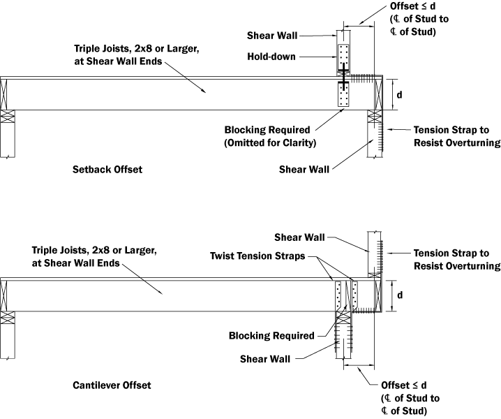
Shear wall story offset provisions were clarified in the 2012 WFCM. Shear wall segments are permitted to be offset out-of-plane from the story below by a maximum distance equal to the depth, d, of the floor joists (Figure 2), where all of the following conditions are met:
- Upper and lower story shear wall segments are attached to the floor diaphragm through wall plate to blocking connection and wall plate to band joist connections
- Floor diaphragm wood structural panel sheathing is nailed to blocking and band joist at 6 inches on-center.
- Allowable unit shear capacity for the shear wall above does not exceed 436 plf for wind or 239 plf for seismic
- Floor joists supporting the shear wall are nominal 2×8 or larger, tripled at ends of shear walls, and provide support for loads from roof and ceiling only
- Continuous load path is provided for uplift and overturning.
Design Values
Design values for structural lumber, structural glued laminated (glulam) timber, and fasteners were incorporated in the integral Supplement of the 2001 WFCM. The 2012 WFCM now references the 2012 NDS Supplement for lumber and glulam design values. For fastener design values, the 2012 NDS is the reference standard.
Shear Wall and Diaphragm Design
Design properties for horizontal diaphragms and shear walls were incorporated in the integral Supplement of the 2001 WFCM. The 2012 WFCM now references the 2008 SDPWS for engineered design of shear walls and diaphragms. Prescriptive tables in WFCM Chapter 3 still contain shear wall and diaphragm tables similar to the 2001 WFCM.
Wind Exposure B & C Tables
Wind Exposure C tables were incorporated in a separate Appendix in the 2001 WFCM. The 2012 WFCM now integrates Exposure B and C tables together in the prescriptive provisions of Chapter 3.
More Details
A comprehensive table listing section by section changes to the WFCM, including modifications to Supplement and Appendix material, is available at www.awc.org.
Conclusion
The 2012 WFCM represents the state-of-the-art for design of one- and two-family dwellings for high wind, high seismic, and high snow loads. Its reference in the 2012 IBC and 2012 IRC will allow for its use in those jurisdictions adopting the latest building code.▪
This article originally appeared in the Winter 2012 issue of Wood Design Focus published by the Forest Products Society and is reprinted with permission.
References
American Society of Civil Engineers. ASCE/SEI 7-10 Minimum Design Loads for Buildings and Other Structures. Reston, VA. 2010.
American Wood Council. 2012 National Design Specification® (NDS®) for Wood Construction. Leesburg, VA. 2012.
American Wood Council. 2008 Special Design Provisions for Wind and Seismic. Leesburg, VA. 2008.
American Wood Council. 2012 Wood Frame Construction Manual (WFCM) for One- and Two-Family Dwellings. Leesburg, VA. 2012.
American Wood Council. 2001 Wood Frame Construction Manual (WFCM) for One- and Two-Family Dwellings. Leesburg, VA. 2001.
Coats, Paul. Use of Wood Structural Panels to Resist Combined Shear and Uplift from Wind. Wood Design Focus. Vol. 20, No. 2. 2010.
International Code Council. 2012 International Building Code. Washington, DC. 2012.
International Code Council. 2012 International Residential Code. Washington, DC. 2012.
Line, Philip and Bill Coulbourne. ASCE 7-10 Wind Provisions and Effects on Wood Design and Construction. STRUCTURE magazine. January 2011.
O’Rourke, Michael, Peter Mazikins, and John “Buddy” Showalter. Snow Provisions of ASCE 7-05. STRUCTURE magazine. December 2006.


