Definitions
Porous: Possessing or full of pores, permeable to liquids.
Porosity: The ratio of the volume of interstices of a material to the volume of its mass.
Volume of Permeable Voids: Volume of space where water or air can permeate.
(From Webster’s 7th New Collegiate Dictionary, B4C Merriam Company, 1972.)
Durability, corrosion resistance and resistance to chemical attack is directly related to concrete’s permeability. If water cannot enter concrete, it cannot cause damage. Penetration of water into concrete is achieved by capillary action through actual physical passageways. Reducing these passageways will increase the resistance of concrete to water penetration.
Certain concretes are watertight and water resistant, as well as strong and enduring in proportion to their absolute densities. Conversely, weak concretes are permeable and of low endurance in proportion to their porosities.
Excess Water as a Cause of Porosity
Aside from segregated pockets of stone which may also be caused by excess water, water voids are quantitatively more important than are air pockets as passageways for penetrating or percolating water. The larger the water to cement ratio, the greater the volume of capillary pores.
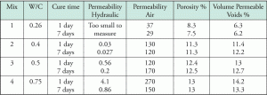
Table 1 illustrates the relationship between water cement ratio, porosity, and permeability in concrete. “The first step in achieving a low permeability is to specify a water cement ratio of 0.4 or less, and then to consider using a supplementary cementing material or blended hydraulic cement”. (Nawy, 1977.)
Shrinkage Forces of Rocks
Flow through porous rock, such as cemented sand or unfractured sandstone, is regular and reliable. Permeability of the rock mass is a reasonably well defined quantity which can be used in analyses. Porous rocks often have a large pore volume of about 10 to 30 percent or more.
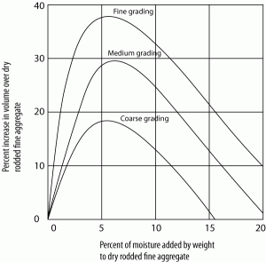
With reference to the Army Corps of Engineers Manual on Rock Foundations, Special Topics – in the “Free Swell Test,” a specimen of rock is ground and put into a tube where water is added and increase in volume is recorded. This bulking is the increase in total volume of moist fine aggregate over the same weight dry, where surface tension in the moisture holds the particles apart causing an increase in volume. If alternate wetting and drying occurs, severe strain develops in some rocks causing an increase in volume and eventual breakdown of the material. Porous concrete will crack similarly.
Table 2 shows the relation between moisture added to dry aggregates versus percent increase in volume. The addition of 5% moisture by weight results in a 25% increase in volume, roughly.
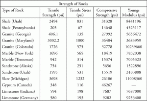
Table 3 provides data on the Strength of Rocks.
Shrinkage Forces on Fresh Concrete
As an example, the following concrete mixture is proportioned by absolute volume where total aggregate may range from 60 to 75%, cement from 7 to 15%, and water approximately 20%.
Cement: 10%
Air: 5%
Fine Aggregate: 25%
Coarse Aggregate: 45%
Water: 15%
Assuming 3000 psi concrete, the tensile strength will equal 6 √f ‘c = 6 x54.6 = 328.6 psi. Although not allowed for major supporting structures, a factor of safety of 3 can be taken to obtain allowable stress in tension.
Taking a factor of safety of 1/3, the allowable tensile stress (P) becomes approximately 100 psi (at design strength) = 14,400 lb/ft².
If we take the allowable stress of freshly placed concrete to equal zero, then from the initial placement to final cure the average tensile stress is roughly 50 psi.
As the volume of the paste decreases by 20% (which is roughly twice the porosity), then this force on the area will be equal to 50 x 0.2 = 10 psi or 1,440 lb/ft2.
To determine the shrinkage force per foot width of concrete, take a 1-foot by 6-inch slab section and determine the length at which it will crack.
A x P = L x A x D or L = P/D
1 ft x 0.5 feet x 14,400 = L x 1ft x 0.5 ft x 1,440 lbs/ft2/ft
L = 14,400/1,440 = 10 feet.
For dry concrete, the porosity is 12%; hence, the force which will crack concrete exposed to dry and wet conditions will be about 12% of the allowable tensile stress.

Figure 1: Surface moisture on fine aggregate can cause considerable bulking, the amount of which varies with the amount of moisture and the aggregate grading. Reference PCA Major Series 172 and PCA ST20
Other examples:
- For rocks, a 25% increase in dry density can more than double the swell pressures developed in the material. The density of the stone is directly related to its tensile stress. Considering an allowable tensile stress of 199 psi for limestone, and taking a 25% increase in the dry density of a facade sample during swelling, then drying – shrinkage forces will approximately equal 25% of the tensile stress of 199 psi or 49.75 psi.
- For unreinforced solid brick masonry with an allowable tensile stress of 7.5 psi, and porosity of 20% from Figure 1, the resultant in a drying shrinkage force will be 1.5 psi.
- For Gypsum, taking a tensile stress of 116 psi will result in a swell pressure of 29 psi. The porosity of gypsum board must be considered in the calculation, as the increase in dry density of the material will be the deciding factor in the pressure. Hence, for a ½-inch thick gypsum board:
½ x (4 ft x12) x P = 116 and P = 5 psi
(will crack if its porosity equals 5%.)
References:
- Concrete Engineers Handbook, McGraw-Hill Book Co, Inc.
- Design and Control of Concrete Mixtures, 13th Edition, PCA, 1994.
- Cast in Place Walls, Concrete craftsman series 2, CCS-2 ACI, 2000.
- Masonry Design and Detailing for Architects, Engineers, and Contractors, Third Edition, Christine Beall, McGraw Hill, Inc., 1993.
- Concrete Construction Engineering Handbook, Edward G. Nawy, CRC Press, 1997.
- Army Corps of Engineers EM 1110-1-2908. Rock Foundations Special Topics.
- Soil Mechanics, SI Version, Lamb & Whitman, John Wiley & Sons, 1979.
- Reinforced Masonry Engineering Handbook, 3rd Edition. J.E. Amerhein, Masonry Institute of America.


