
By Fatemeh Shirmohammadi, Ph.D, PE, SE, H. Aydin Pekoz, Ph.D, PE, and Kevin Poulin, Ph.D, PE
Click here to view the article with images and equations in the digital flipbook.
Located in Midtown Manhattan, an art gallery holds a prime position in showcasing modern and contemporary art. (The name and the address of the gallery are confidential per the gallery owner’s request.) The two-story building was constructed in the 1930s with an approximate building area of 28,000 square feet. The superstructure consists of concrete floors supported by concrete-encased steel beams and cast-iron columns. The perimeter walls are brick masonry construction.
A neighboring gallery within the same building left their space, and as a result, the gallery decided to renovate the building to expand into that space. In February 2022, Ryall Sheridan Carroll Architects and Simpson Gumpertz & Heger Associates Inc., P.C. (SGH) began work on the project. Based on a set of existing renovation drawings, the building seemed to have been renovated once during its service life in 2012. This renovation consisted of a new skylight, a new stair, and two steel roof dunnage platforms that were added at the west side of the building.
Investigation Phase
Without the benefit of design drawings for the original construction, SGH conducted an extensive investigation in the areas affected by the proposed scope of work, in which the team documented the structural elements of the existing building, including foundation details, beam and girder sizes, slab composition, column dimensions, and structural connections (Figure 1). In total, the contractor opened 17 exploratory probes and excavated two test pits. SGH limited the number of probes and test pits by using comparative-loading analysis as much as possible.
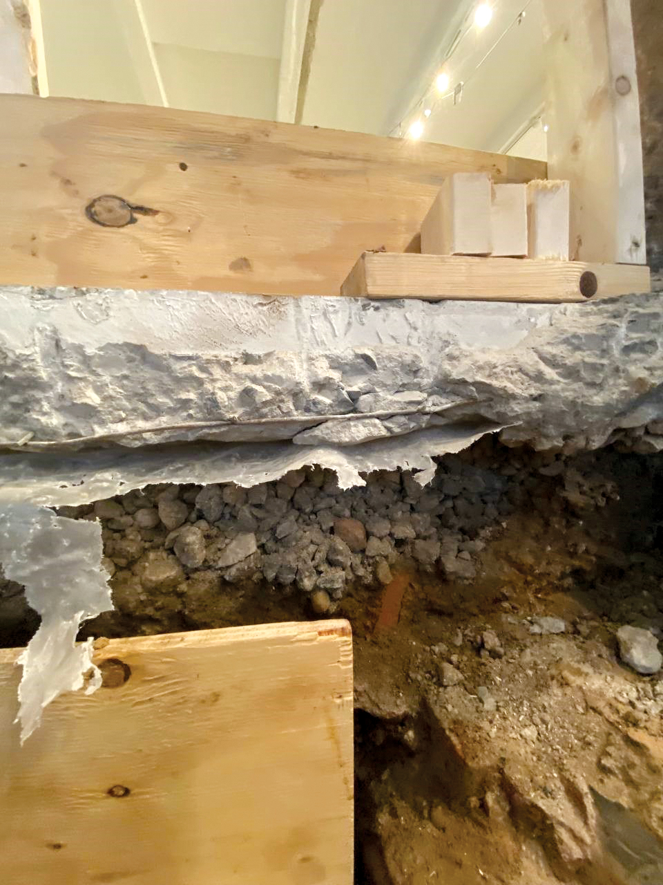
The ground floor is a 5-inches-thick concrete slab-on-grade with 4×4 welded wire reinforcement (WWR) as the main reinforcement. SGH observed a layer of waterproofing membrane on a 5-inch-thick layer of crushed stone below the slab-on-grade (Figure 2).
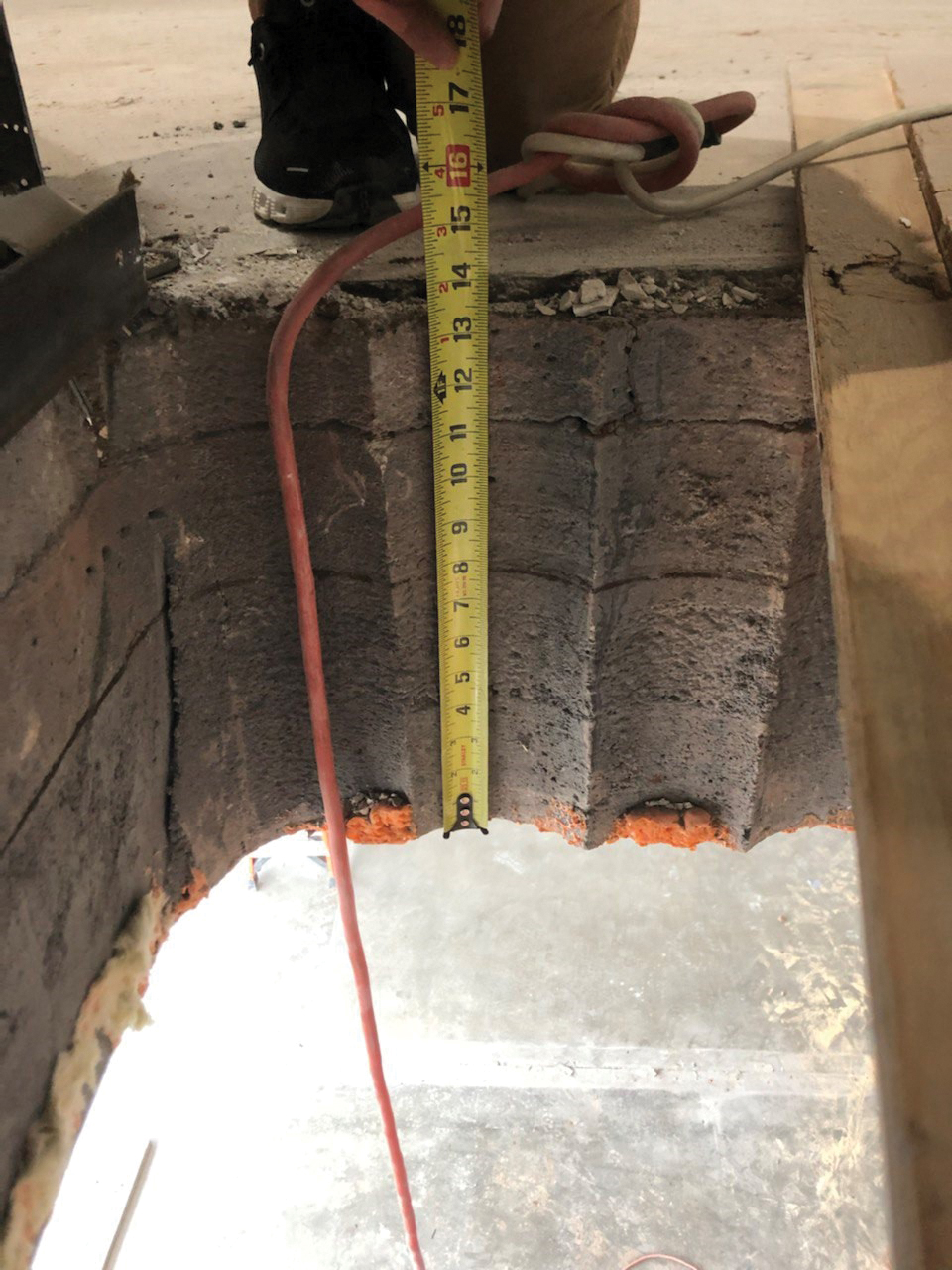
The superstructure floors include draped mesh cinder concrete slabs with two layers of cinder fill. The second-floor slab has a total thickness of 13-1/2 inches with a composition of 8-inch cinder concrete slab, 3-1/2-inch cinder fill, and 2-inch cement topping (Figure 3). The roof slab has a total thickness of 6-3/8 inches with a composition of 4-inch cinder concrete slab and 2-3/8 inch cement topping. The cinder concrete slabs are supported by steel beams and girders encased in cinder concrete. The floor framing is supported on 8-inch diameter cast-iron columns with ¾-inch or 1-inch wall thicknesses within the interior of the building. Along the perimeter of the building, the floor framing is pocketed into the masonry brick walls.
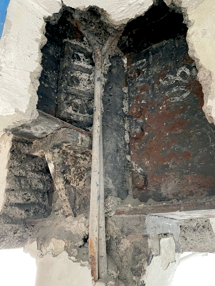
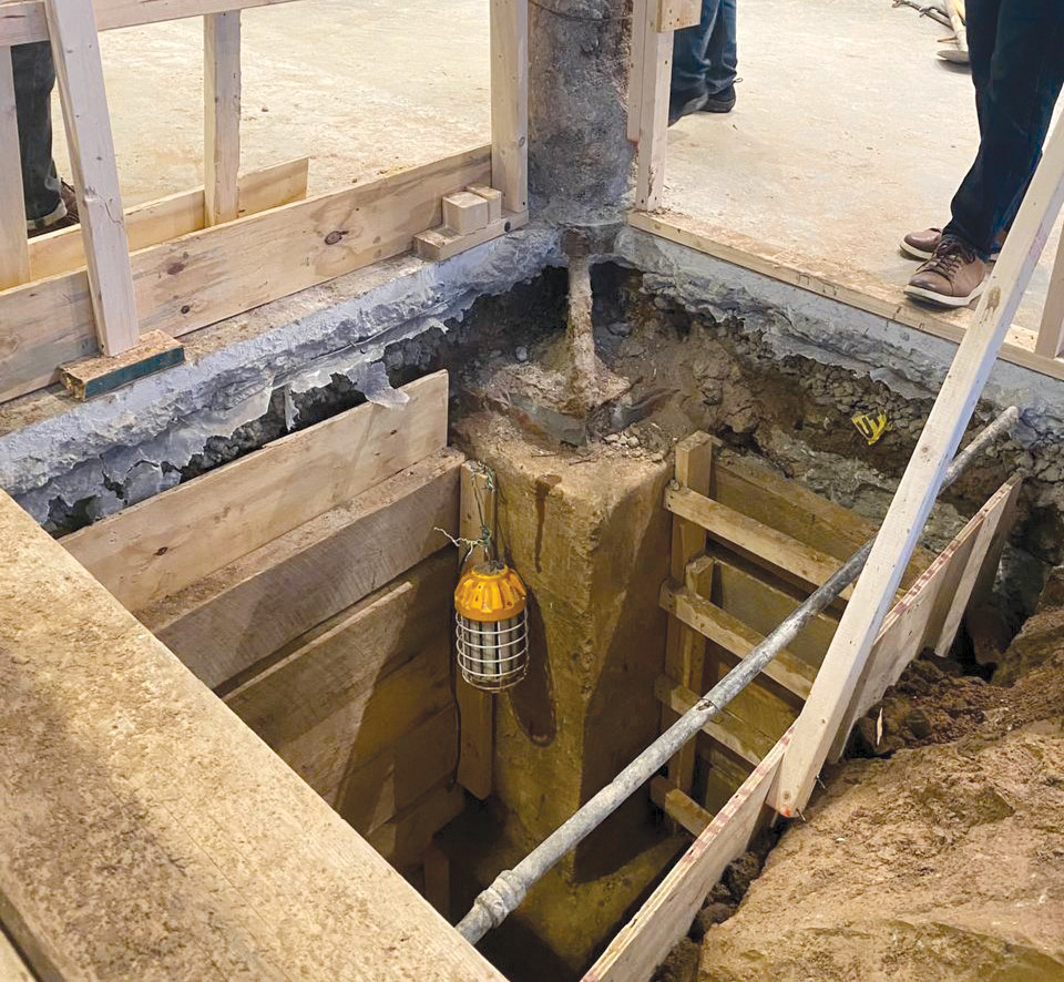
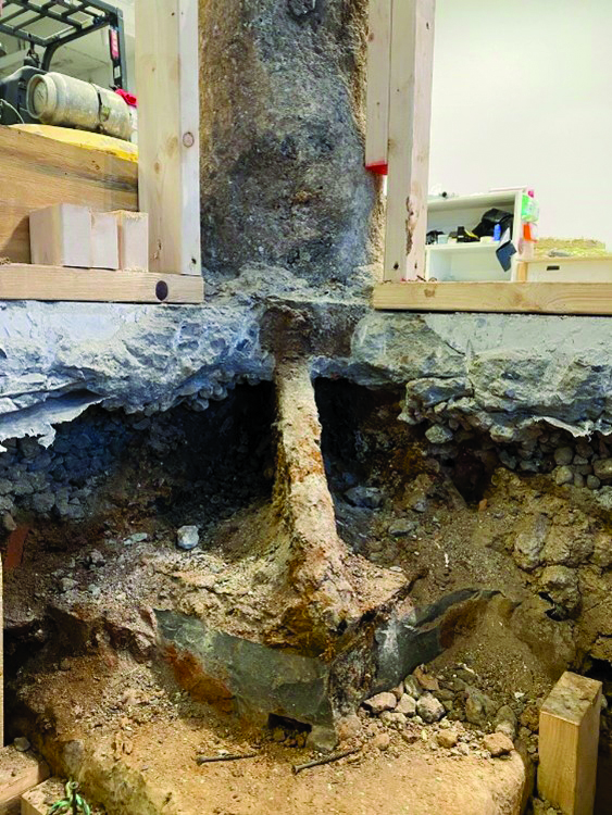
Test pits revealed that a typical cast-iron column has a 4-inch thick and 2-foot, 8-inch by 2-foot, 8-inch steel base plate with eight 1 7/8-inch thick vertical stiffeners. The base plates are supported by an approximately 4-foot deep concrete pilaster on a 5-foot by 5-foot isolated footing (Figure 4).
Design Phase
The proposed structural renovations throughout the building included the expansion of open gallery space on the ground floor, a new skylight at the roof level, a new platform at the roof level to showcase artwork, and a new dunnage at the roof level to support upgraded mechanical equipment.
Expansion of the Open Gallery Space
Expanding the open gallery space on the ground floor required the removal of one existing cast-iron column and the installation of a new steel column. SGH proposed that the contractor install temporary shoring, remove the cast-iron column, install a new steel column on a new spread footing at a new location, and reframe the structural bay. For this approach, however, the span between the new steel column and an existing cast-iron column in the next grid became 10 feet longer, and the unfactored gravity loading on the next grid’s existing column increased by 26% compared to its as-built condition. This load increase was much larger than the 5% gravity-load threshold of the prescriptive compliance method (5% rule) of the International Existing Building Code (IEBC). Thus, the capacity of this existing cast-iron column needed to be analyzed. Several methods were evaluated for this task.
In the 1938 New York City Building Code (1938 NYCBC), the following formula is provided to calculate the allowable working compressive stress in cast-iron columns:
Eq. 1where L and r are column length and radius of gyration, respectively.
This formula is the lowest-value straight-line formula used in New York City and represents a 20% reduction from the historic formula that was in use from 1899 to 1916. Typically, straight-line formulas are not satisfactory in predicting the performance of columns, especially when their behavior is buckling-dominated. Considering the results of experimental studies on the behavior of full-size cast-iron columns by Paulson et al. (1996), the 1938 NYCBC formula is shown to overestimate the capacity of short columns (L/r<40 ) and underestimate the capacity of taller columns (L/r>40 ft.). In addition, this formula is only applicable to columns with an L/r ratio less than 70.
Another method that is available is the column formula originally proposed by Paulson et al. (1996), which was later re-evaluated by Paulson (2013). The original Paulson et al. (1996) formula was developed through statistical analysis of test data obtained during the 1880s and 1890s on full-size cast-iron columns. In their study, Paulson et al. defined the nominal capacity of the column (Pn) as the resultant of the column cross-section area (Ag) multiplied by the critical stress (Pn=Fcr×Ag).
They calculated critical stress (Fcr) based on the column’s slenderness ratio as follows:
Eq. 2Using a load and resistance factor design (LRFD) approach, the column axial strength check is simply calculated as:
Eq. 3Where Pu, Pn, and ϕ are the LRFD factored column axial force demand, the nominal capacity of the column calculated as described above, and the resistance factor, respectively. In order to approximate the resistance factor, Paulson et al. (1996) performed a reliability analysis of an allowable stress design (ASD) procedure of the 1993 BOCA Code and calculated a reliability factor. As a result, a resistance factor, ϕ=0.65 was recommended for the LRFD approach having the same reliability.
Using the ASD approach, the column axial strength check is simply calculated as follows:
Eq. 4Where Pa is the column axial force demand, and Ω is the factor of safety, which is calculated as Ω=1.5/ϕ per AISC 360. Considering ϕ=0.65, the factor of safety Ω is calculated to be 2.3.
Calculations of the existing column capacity using the method established by Paulson et al. (1996) showed that the column would be overstressed by 9% under the new loads. Therefore, the existing column needed to be strengthened or replaced. SGH evaluated various strengthening strategies for the existing column, including steel jacketing, fiber-reinforced polymer (FRP) wraps, and reinforced concrete jacketing. None of these strategies proved to be structurally or economically feasible or architecturally preferable, as explained below:
In theory, a new steel jacket can be welded or bolted to the existing cast-iron column. The welding option was not considered because of difficulties in welding cast iron and the potential for cracking the column during welding. Bolting the steel jacket to the existing cast-iron column was not cost-effective. In addition, transferring the new loads into the new steel jacket portion would have required further investigations and potentially non-feasible detailing. Therefore, this option was not implemented.
The American Concrete Institute (ACI) Committee 440, Report on Fiber-Reinforced Polymer (FRP) Reinforcement on Concrete Structures, imposes strengthening limits for structural concrete strengthened using FRP to guard against failure of the strengthened elements, should the FRP reinforcement become ineffective because of fire, substrate degradation, vandalism, or impact damage. Due to the lack of specific standards for cast-iron columns with FRP strengthening, SGH decided to implement ACI 440 in our evaluations as a guide.
The imposed limitations require that the member to be strengthened should have a minimum strength (φRn) to resist new sustained loads without any contribution from the FRP wrap. The sustained load is defined as 110% of the new dead load and 75% of the new live load. ACI 440 recommends a reduction from the conventional factor of 1.2 to 1.1 for the dead load in the load combination to take advantage of the relatively accurate determination of existing dead loads. The live load factor of 0.75 is used to ensure that the considered live load factor exceeds the American Society of Civil Engineers Minimum Design Loads and Buildings and Other Structures (ASCE 7) statistical mean of yearly maximum live load factor of 0.5. ACI 440 also recommends that if the design live load acting on the strengthened member has a high likelihood of being present for a sustained period, the live load factor should be increased to 1.0.
Using estimates of cast-iron column capacity using Paulson et al. (1996) and the above principles of ACI 440, the cast-iron column could not be strengthened using FRP wraps to resist the new demands.
Creating a reinforced concrete cage around the existing column resulted in a column dimension that was too large for the open space requirements of the gallery and, thus, was not feasible to implement.
Eventually, replacing the column was the most feasible structural solution.
Based on the geotechnical requirements from the project geotechnical engineer, the footing needed to be enlarged to keep the soil bearing pressures due to the new loads within the allowable limits.
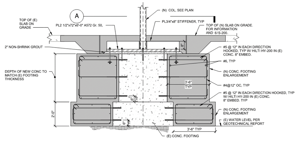
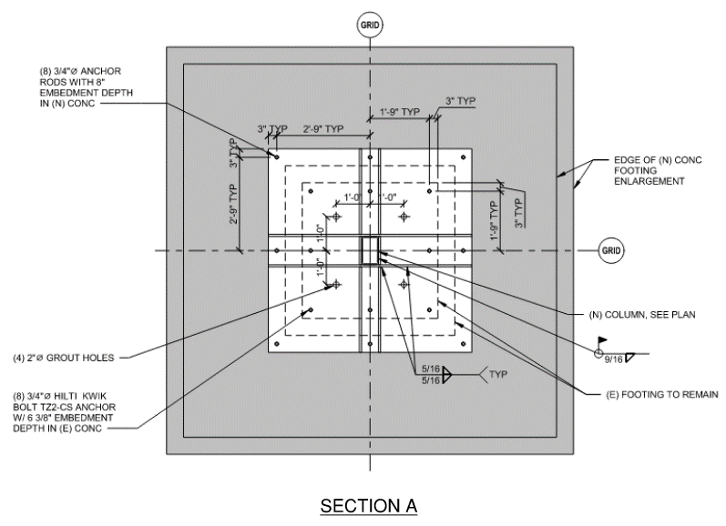
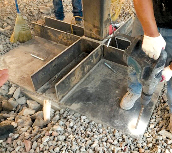
SGH designed a new tube column supported on the existing pilaster and the footing, which were strengthened by adding reinforced concrete rings around their perimeters. The new rings were doweled into the existing pilaster and the footing. SGH designed a 2-1/2 inch-thick base plate with eight ¾-inch-thick vertical stiffeners to create a direct load path and transfer the loads from the new column to the enlarged portion of the pilaster. The new base plate was anchored using mechanical anchors and cast-in-place anchors into the existing pilaster and into the enlarged portion of the pilaster, respectively (Figure 5 and Figure 6).
Structural Modifications on the Roof
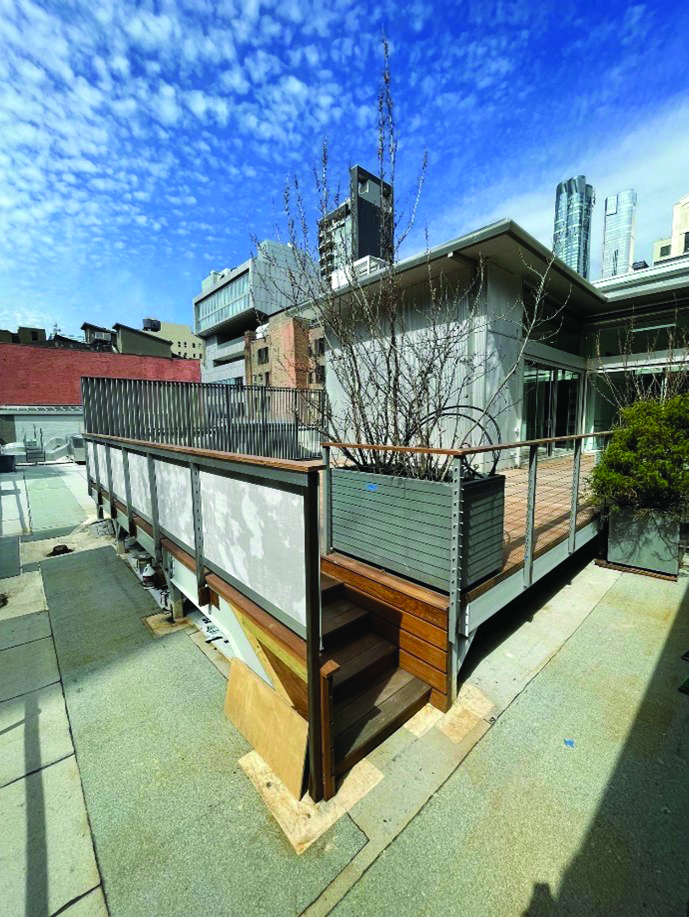
The main goal was to design the dunnage and the exhibition platform to avoid any strengthening work to the original structure. SGH coordinated the location and the layout of the new dunnage with the mechanical engineering consultant so the new loads imposed on the existing structural framing do not violate the 5% rule. Regarding the exhibition platform, SGH evaluated various factors to comply with this rule: the extent of the platform, the location of support posts with respect to the existing roof framing, the height of perimeter screen walls, the live load rating of the platform, and the type of structural framing. As a result, the plan area of the exhibition platform was reduced, and the screen walls were slightly lowered from the prior design.
In addition, the live load of the platform was reduced to 50 psf using the NYCBC Section 1004 occupant load criteria. The platform was designed to have plywood sheathing supported on 2-inch x 8-inch wood joists at 16 inches in center spanning between steel girders that connect to new steel posts (Figure 7). This minimized the loads imposed on the existing structure, and the requirements of the 5% rule were met.
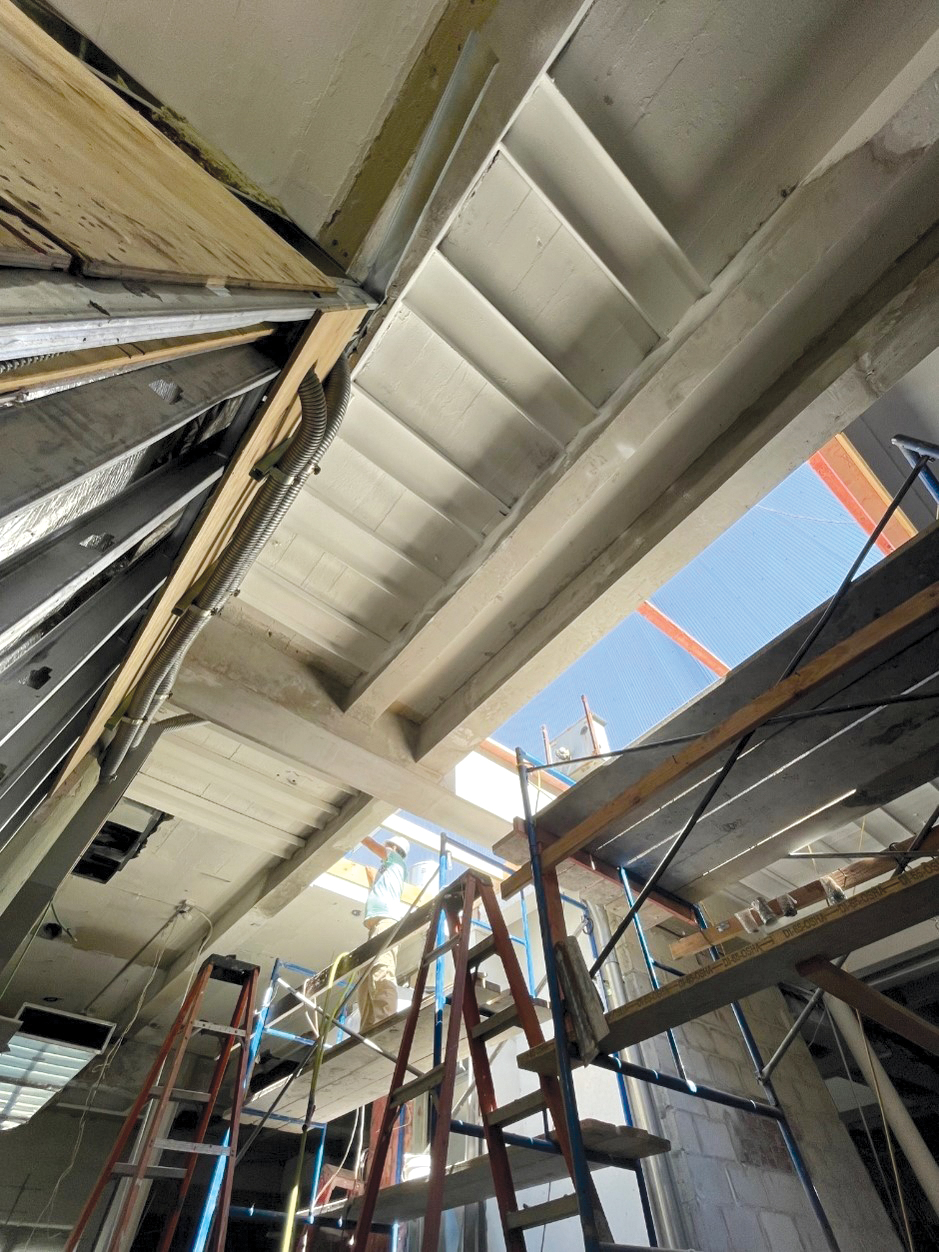
SGH followed the requirements of the 1968 NYCBC (the latest version of the code that specified requirements for draped-mesh cinder concrete slabs) to create the new skylight opening in the existing cinder concrete slab (Figure 8). According to this code, a single opening larger than 18 inches on a side and multiple openings aggregating more than 18 inches (in any 10-foot width or span of the slab) must be framed. The proposed skylight opening exceeded the opening size threshold of the 1968 NYCBC. Thus, SGH designed new steel beams to frame the opening.
In cinder concrete slab construction, a typical interior span has approximately 40% more capacity than an equally reinforced end span when the reinforcing mesh is continuous over supporting steel beams. SGH analyzed the cinder concrete slab in bays adjacent to the skylight opening, considering mesh discontinuity at those bays. SGH used the empirical equations of the 1968 NYCBC to calculate the capacity of the slab, considering the main reinforcement cross-sectional area, the clear distance between steel beam flanges, the type of concrete (stone or cinder), and the reinforcement attachment at supports (continuous or anchored/hooked).
The analysis results show that the existing slab on the adjacent bays would be overstressed by 23% after creating the skylight opening and thus needed to be strengthened. To strengthen the slab at adjacent bays, SGH designed flat channels below the existing slab spanning between existing steel beams.
Construction Phase
SGH delegated the design of the steel connections to the fabricator’s engineer. In accordance with the American Institute of Steel Construction Code of Standard Practice for Steel Buildings and Bridges (AISC 303), SGH, as the project’s Engineer of Record, is still responsible for the adequacy of the primary structural system, including connections. Per the requirements in the project specifications, the fabricator’s engineer submitted signed and sealed calculations for SGH to review. The connection calculations were performed using a software called IDEA StatiCa, which is widely used in Europe. The software uses component-based finite element modeling (CBFEM) to design the connections. The software output includes graphs showing stress and strain distributions for various parts of connections and demand-capacity ratios for each part of the connections.
AISC Specification for Structural Steel Buildings (AISC 360) allows the option of using finite element analysis for designing steel components of the structure. As part of the review of connection calculations, SGH validated the results of the software by analyzing several connections with high levels of loadings using the design requirements of AISC 360. The differences between the demand capacity ratios of the connections reported by the software and SGH calculations were negligible.
Timeline
The gallery’s main requirement at the inception of the project was to accelerate the investigation, design, and construction schedules to avoid downtime for the gallery’s public service. SGH provided the engineering solutions in approximately three months for the investigation and design. The construction lasted about five months, with quick turnaround times for the review of submittals and Requests for Information (RFIs). During these phases, the gallery remained open to the public with only partial shutdowns.
Conclusion
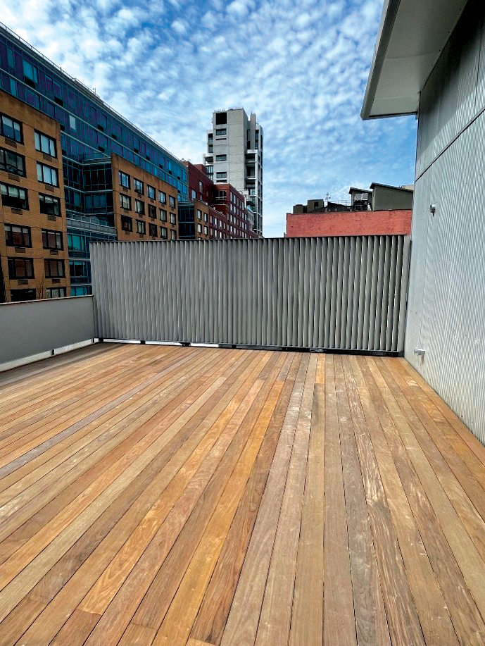
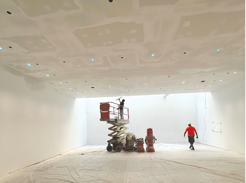
The gallery expanded into the neighboring gallery and renovated its space to host events, exhibitions, and art fairs. The gallery fully reopened in October 2022. The project team designed and executed modifications to improve the experience for visitors and to allow them to enjoy the works of art better. The expanded open space on the ground floor provides a wide-open atmosphere without obstructions (Figure 9). The platform at the roof creates an inviting space to showcase artwork with an expansive view of the blue sky above. ■
About the Authors
Fatemeh Shirmohammadi, Ph.D, SE, PE, is a Senior Consulting Engineer in the Structural Engineering Group of Simpson Gumpertz & Heger Inc. (SGH). Fatemeh has more than nine years of experience in designing new structures and evaluating and designing repairs for distress related to concrete, steel, masonry, and wood structures.
H. Aydin Pekoz, Ph.D, PE, is a Senior Project Manager in the Structural Engineering Group of SGH. Aydin has more than 15 years of experience in the structural analysis and design of new structures.
Kevin C. Poulin, Ph.D, PE, is a Principal in the New York office of SGH, with over 30 years of experience as a structural designer, including renovation of existing buildings, design of new buildings, structural peer reviews, condition assessments, and feasibility studies.