
Traditional construction methods such as stick-framing cold-formed steel (CFS) walls have been in use for a long time. Stick framing involves wastage of material and requires skilled field labor, slower build time, and scheduling around favorable weather. With advancements in technology, we are now witnessing the early stages of innovation in the architecture, engineering, and construction (A/E/C) industry using automation.
CFS projects have been at the forefront of adopting these emerging technologies, setting a precedent for the A/E/C industry. Robots have become integral to the CFS world, providing CFS framing industries with a competitive edge through automation, increased safety, and enhanced production. Applying these technologies creates efficiencies and introduces new challenges for individuals in the A/E/C industry.
In the world of CFS, automation through robots plays a vital role in every step of the manufacturing process by: 1.) Automating the roll forming process to various shapes and sizes of CFS. 2.) Using robotic arms for framing CFS into panels or pods and adding sheathing to the panels. 3.) Automating rasping using CNC machines. 4.) Using robots to spray and sand interior walls. And 5.) Deploying field printer robots to position walls/pods accurately in the field.
Robots in the CFS World Automating the Roll Forming Process
The traditional stick-framing process involves preordering and procuring large quantities of material. At the construction site, the studs are cut to the required length and dimensioned on the track per the engineering drawings. Alternatively, using an automated roll former, the studs and tracks are rolled precisely to spec using the digital BIM models, reducing wastage and rework.
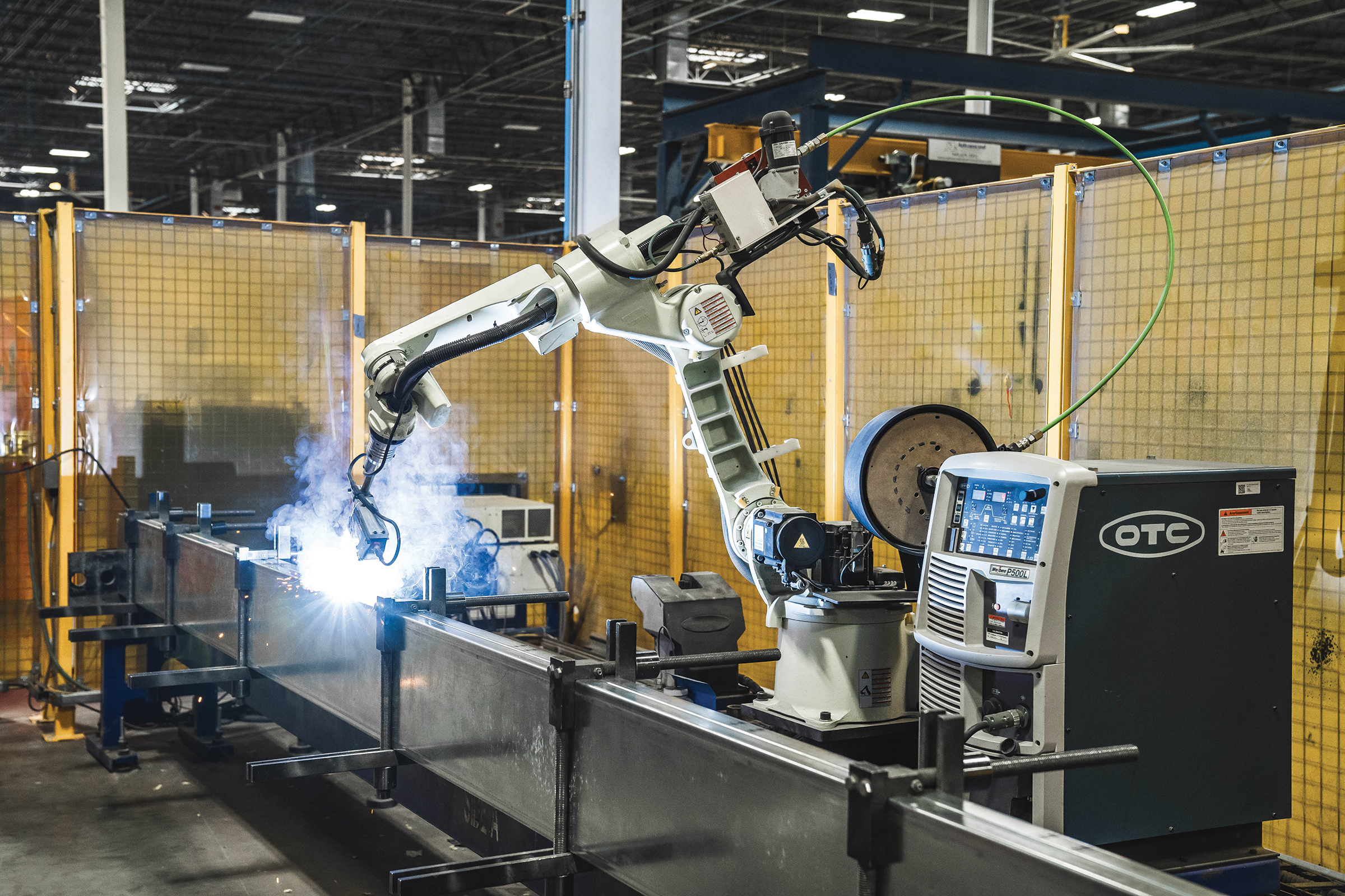
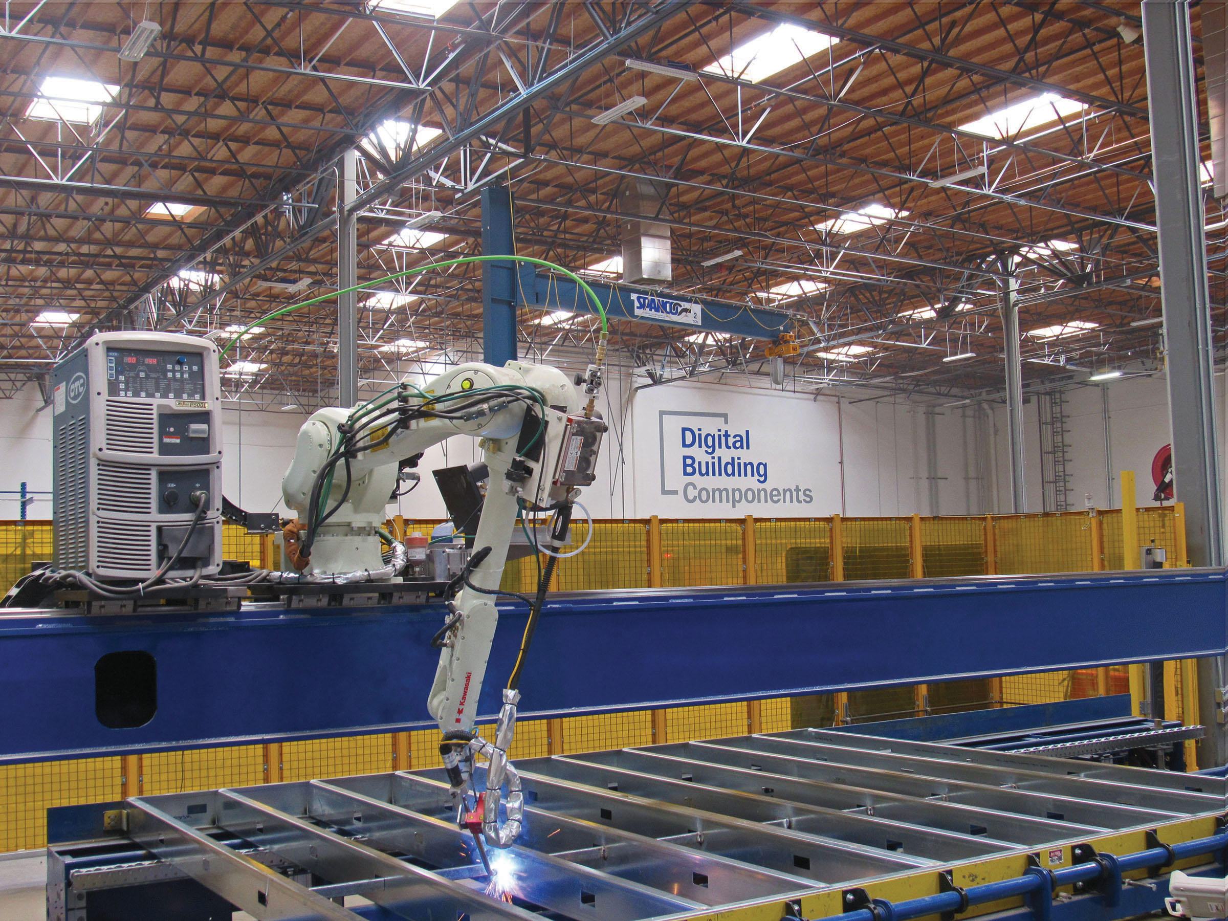
Robotic Arms for Framing and Sheathing
Resembling a human arm mounted to a base, a robotic arm offers multiple degrees of freedom. Its primary application includes welding sub-assemblies together, such as stud-to-track welds, built-up stud components, and CFS-to-structural steel welds. These robots also weld entire panels by utilizing custom welding torches to reach intricate weld positions in the frame. The weld positions are precisely defined in 3D space with BIM software. The generated CAD files are further used to simulate the robot path. This capability extends to welding joints like lap, flare bevel, and other welds as well as welding materials up to 20–22-gauge galvanized steel. Laser profile scanners attached to the robot’s end-effector are used to find deviations in the CFS frame within fabrication tolerances before welding.
However, robotic arms are sensitive to material tolerances. For example, AISI 240 allows up to 1/8 inches between stud-to-track gaps for load-bearing walls and ¼ inches for curtain walls using 16-gauge material. Deviations in wall plumbness, straightness, and levelness can affect robot welding quality. Incomplete fusion/burn-through of CFS materials is a potential issue, demanding quality check inspection.
Spot welding addresses some of the issues associated with robots doing fillet welds. However, spot welds have lower allowable capacity than fillet welds, necessitating project-specific considerations.
Robotic arms are also employed for tasks like screwing studs to tracks and placing heavy sheathing boards. The software can be customized to add screws at specific locations and required spacing.
Automating Rasping Using CNC Machines
Rasping is a technique used to make the surface of EPS/insulation board even and flat before applying finishes. This method produces tiny beads of EPS which when inhaled creates health risks. CNC rasping machines are used as an alternative to hand rasping for finishing panels. These machines use larger-diameter bits to rasp panels, achieving acceptable roughness and precision efficiently. Next-generation rasping CNCs can be designed with additional degrees of freedom for cutting out reveals and adding slopes in EPS with high precision.
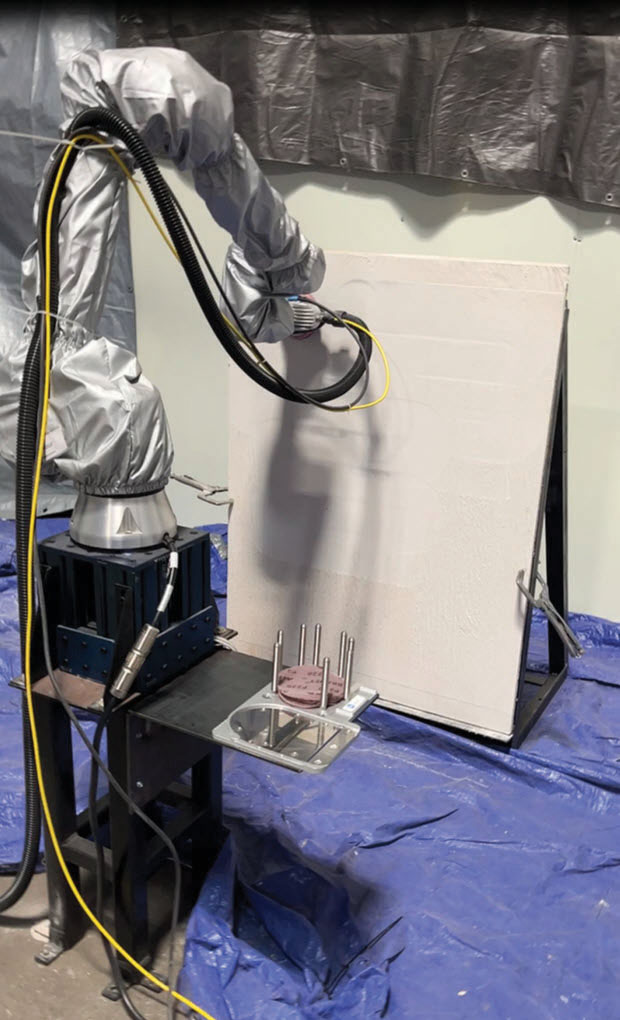
Spraying and Sanding Robots
These robots have been employed on construction sites for spraying drywall mud, sanding, and applying paint. At construction sites, they move on wheels and scan the room to add finishes to the wall. Similarly, spraying and sanding processes can be performed in the prefab shop with fixed robots while panels move on conveyors within a paint booth, thereby increasing productivity and safety.
Field Printers
Robots are employed to mark layouts of wall panels/pods on slabs, enhancing accuracy and reducing human error. A 2D layout drawing is given as input to the field printer robot including the locations, and the sizes of MEP penetrations. Current field printers require human attention to navigate obstacles and for initial setup. Future iterations of field printers have the potential to use Lidar technology that can be integrated to navigate obstacles and define slab boundaries.
Conclusion
The integration of robotic technologies has brought increased efficiency, precision, safety, and competitiveness to every stage of CFS construction. Robots have revolutionized the CFS industry by increasing productivity and efficiency throughout the construction process. However, challenges related to material tolerances and specific project requirements must be carefully considered when implementing robotic technologies in CFS projects.■