
Many welds are evenly loaded: the applied loads are uniformly transferred through the throat and length of the welds. Such welds are easily designed and routinely perform as expected. Other welds, however, are unevenly loaded. One end of the length of the weld may be more severely loaded than the other, or the loading along the weld throat may be non-uniform. The design of these welded connections is more complicated.
Fortunately, design codes dealing with welded connections, such as the American Institute of Steel Construction’s AISC 360, Specification for Structural Steel Buildings, and the American Welding Society’s AWS D1.1, Structural Welding – Steel, provide design rules to accommodate unevenly loaded welds. The unfortunate situation is that engineers and detailers involved with the design of welded connections may be unaware of the need to treat such connections in a special manner. When unevenly loaded welds are treated incorrectly, the performance of the welded connection will likely be compromised.
This article summarizes five of the ten most frequently encountered conditions involving unevenly loaded welds. The remaining five conditions will be covered in Part 2 of this article in the March issue of Structure Magazine.
Condition 1: Unevenly Loaded Because of Bending About the Root of Fillet or PJP Groove Welds
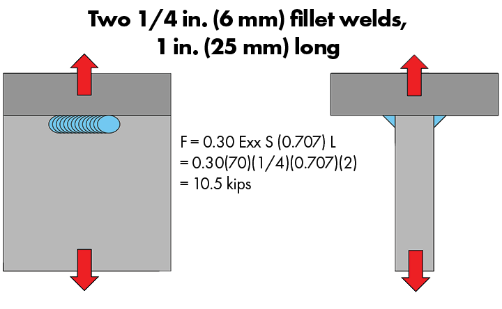
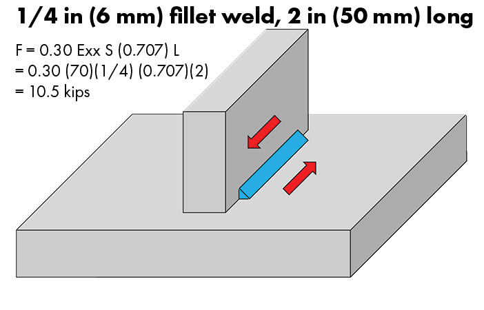
Consider two ¼-inch fillet welds on either side of a tee joint, each with a length of 1 inch, as shown in Figure 1. The calculated capacity of this pair of fillet welds is 10.5 kips when loaded in tension or in shear. Next, consider the same amount of fillet weld but placed on one side of the joint (i.e., a single ¼-inch fillet weld that is 2 inches long), as shown in Figure 2.
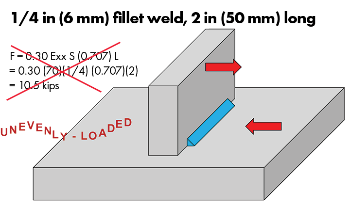
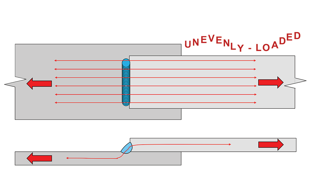
The capacity of the fillet weld shown in Figure 2 is the same as the weld shown in Figure 1 if loaded in shear. However, if loaded in bending, as shown in Figure 3, the weld is unevenly loaded: strains are concentrated in the weld root, and the capacity of the welded connection will be significantly reduced. The same condition occurs with partial joint penetration (PJP) groove welds. The uneven loading shown in Figure 3 should be avoided.
The AISC Steel Manual (AISC 2023) offers this advice: “When lateral deformation is not otherwise prevented, a severe notch effect can result, as illustrated in Figure 8-10 . The use of a single-sided fillet or PJP groove weld in joints subject to rotation about the toe of the weld is discouraged. Using a weld on each side will eliminate this condition.”
One solution, as listed in the manual, is to use double-sided welds, as shown in Figure 1. If double-sided welding is not possible, stiffeners or gussets can be used to preclude rotation about the weld root. The key is to eliminate any joint rotation that will result in tension about the root of the single-sided weld.
Condition 2: Unevenly Loaded Because of a Single Transverse Weld in an End-Loaded Lap Joint
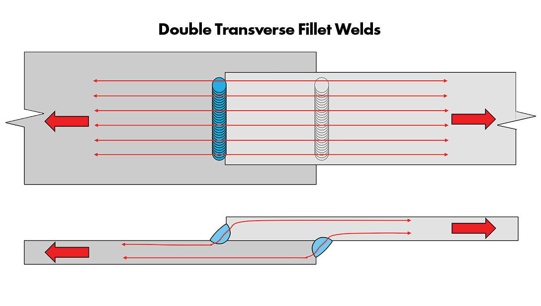
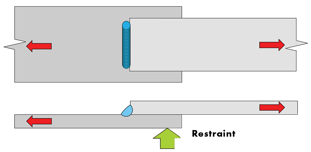
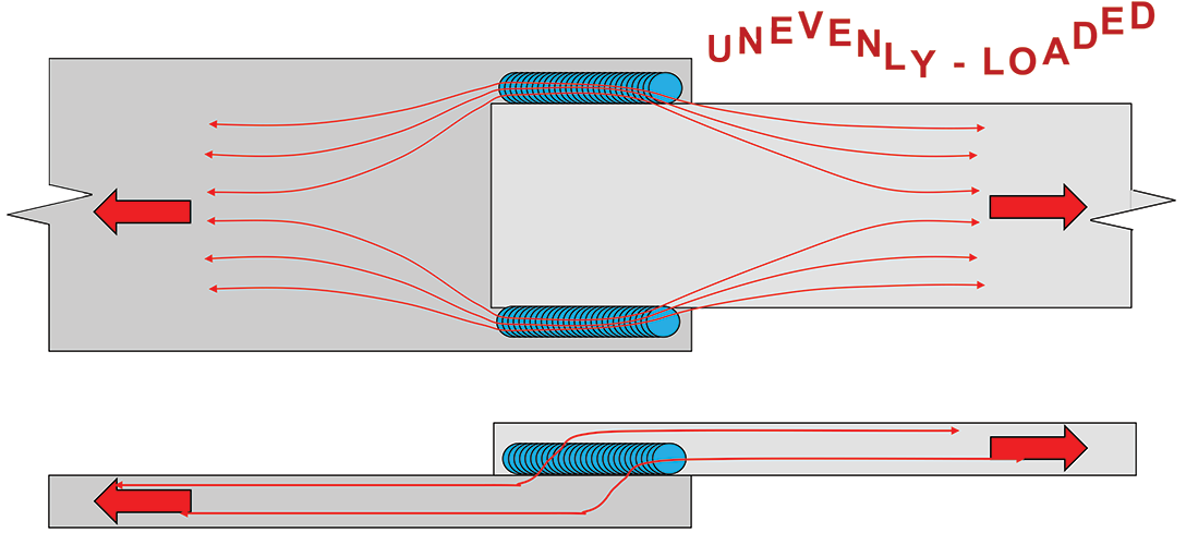
End-loaded lap joints are typically detailed with double transverse fillet welds, as shown in Figure 4. While there is some local eccentricity associated with the connection, no special precautions are needed for this condition. Under some conditions, it may be impossible to obtain access for welding on the second side of the joint, resulting in the conditions shown in Figure 5. This is a problematic configuration, prohibited by AISC 360 (AISC 2022) as follows: “Lap joints joining plates or bars subjected to axial stress that utilizes transverse fillet welds only shall be fillet welded along the end of both lapped parts, except where the deflection of the lapped parts is sufficiently restrained to prevent opening of the joint under maximum loading.”
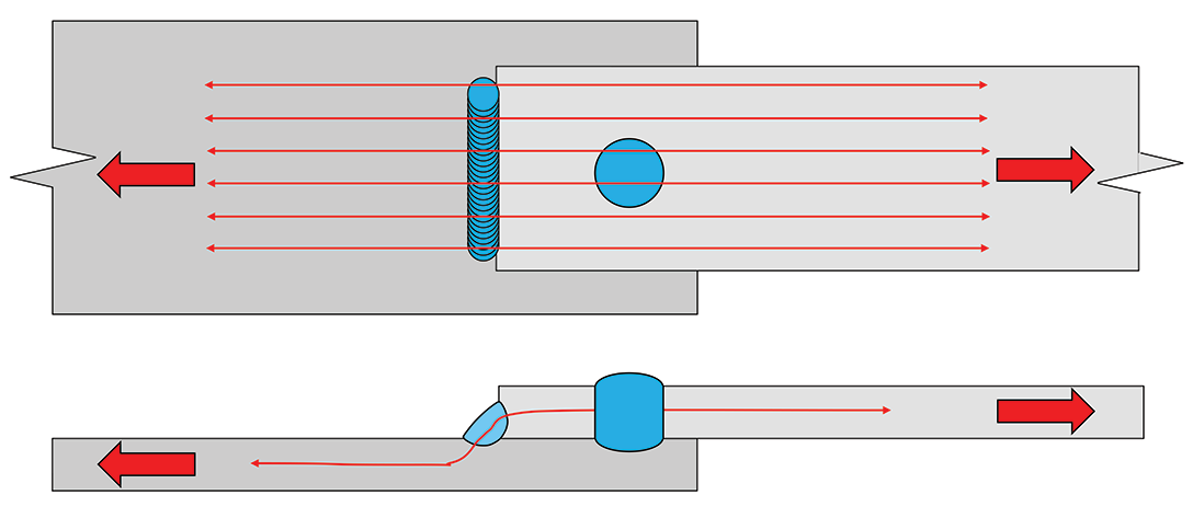
When it is impossible to weld along the ends of both lapped parts, the restraint needed to prohibit the opening of the joint may be achieved through the stiffness of the joined members or a mechanical support, as shown in Figure 6. A plug or slot weld on the accessible side of the joint is another potential solution, illustrated in Figure 7. Longitudinal fillet welds may also be an acceptable alternative.
Condition 3: Unevenly Loaded Because of Short Spacing Between Transverse Welds in End-Loaded Connections
The third condition is the same as discussed in Condition 2 but focuses on the overlap dimension as compared to the number of welds. The eccentricities associated with end-loaded lap joints can be typically ignored; however, when the overlap dimension is too small, these eccentricities can result in unevenly loaded welds.
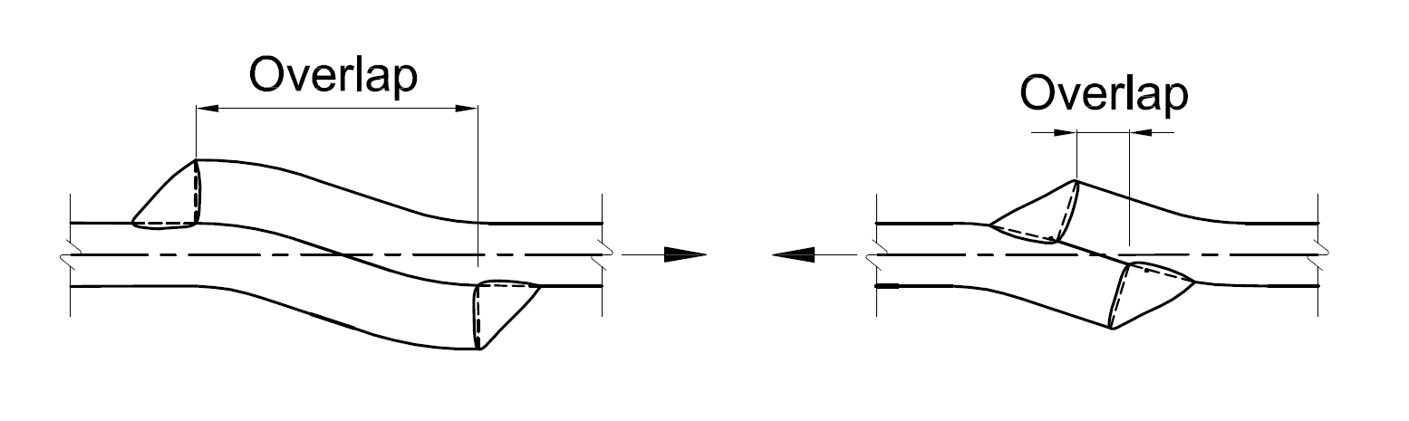
AISC 360 requires the following: “In lap joints, the minimum amount of lap shall be five times the thickness of the thinner part joined, but not less than 1 in. (25 mm).” This concept is illustrated in Figure 8, Part A. The unacceptable condition is shown on the right-hand side of Figure 8. Localized rotation of the connection will concentrate strains at the weld toe, resulting in uneven loading.
Condition 4: Unevenly Loaded Because of Shear Lag
Welds may be unevenly loaded because of shear lag. Shear lag is defined in the glossary of AISC 360 as “Nonuniform tensile stress distribution in a member or connecting element in the vicinity of a connection.” The concept of shear lag is illustrated in Figure 9, where an end-loaded lap joint is shown. For this condition, AWS D1.1 Clause 4.9.2 offers a simple solution: “If longitudinal fillet welds are used alone in lap joints of end connections of flat bar or plate members, the length of each fillet weld shall be no less than the perpendicular distance between them.”
AISC 360 Table D3.1 provides shear lag factors for other geometric configurations where some, but not all, of the cross-sectional elements are joined by welds or mechanical fasteners. The shear lag factor “U” is a reduction factor, always less than 1.0, that accounts for the unevenly loaded condition. Two primary factors are used to determine “U”: the length of the weld and the distance of the weld from the neutral axis, identified as x-bar. To reduce the shear lag factor (that is, to achieve a value closer to 1.0), the weld length can be increased, or x-bar can be reduced. In most cases, increasing the length of the weld is the simplest solution. This inevitably requires increasing the amount of overlap in the connection.
Condition 5: Unevenly Loaded Because of a Long Weld in an End-Loaded Connection
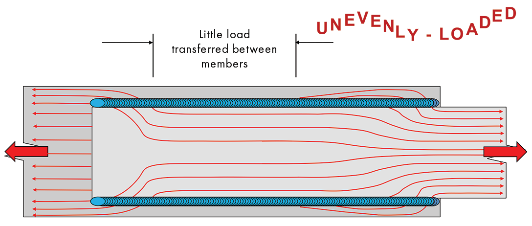
Condition 5 is the opposite of Condition 4: rather than having a weld that is too short, this condition occurs when the weld in an end-loaded connection is too long. As shown in Figure 10, for very long welds in end-loaded connections, the majority of the load is transferred through the ends of the long welds, with relatively little load transferred through the center.
AISC 360 addresses this condition by providing three relationships that compare the fillet weld leg size “w” to the fillet weld length “l.” When the length “l” is less than 100w, no adjustment is required. In other words, the weld is considered evenly loaded when l < 100w.
For weld lengths of 100w – 300w, the effective length is modified by this relationship:
β = 1.2 – 0.002(l/w) < 1.0The actual length “l” is multiplied by the β factor, reducing the length permitted to be used for calculation purposes.
Finally, for lengths greater than 300w, the effective length is fixed at 180w.
These relationships apply to end-loaded connections; they do not apply to longitudinal welds that are used to join webs to flanges on plate girders where the weld is subject to shear due to bending.
While the described design rules are valid, these conditions very rarely occur. For example, consider a 5/16-inch fillet weld, where 100w is 31 inches; up to this length, no consideration of the effect of long weld length is needed. For this weld, 300w is 94 inches; this is the point where the effective length becomes fixed at 180w, or 56 inches. Only very large end-loaded connections will be affected by these provisions.
Preview for Part 2
Uneven weld loading due to other common conditions, such as combining transverse welds with longitudinal welds or using welds in combination with bolts or rivets, will be discussed in Part 2 of this article in the March issue of STRUCTURE. More detailed information on how to mitigate these conditions can be found in AISC 360, the AISC Steel Construction Manual, and in AWS D1.1. ■