
Streamlining the design process for slabs-on-grade that support heavy racking loads.
Slab-on-grade (SOG) is a very important structural component for an industrial facility as it directly supports the building racking system and its loads. The rack loads are influenced by various factors, including pallet weight, pallet height, building clear height, and seismicity. Rack loads act as point loads in both downward and upward directions. Design and analysis of the slab is typically done by numerical modeling and finite element analysis, which is time-consuming and not easy to perform. In this article, a quick and easy design tool is developed based on a parametric study of buildings with different pallet weights, seismicity, and slab thickness and regression analysis of a cluster of data. From this quick lookup tool, it becomes very easy to estimate the slab’s capacity in terms of pallet weight, given the slab thickness and seismicity. Moreover, an adjustment table is developed to calibrate the results of buildings with different clear heights. This tool, combined with the adjustment table, helps the design team and/or owner make a quick decision in terms of building racking functionality at an early stage.
Warehouse Racking System
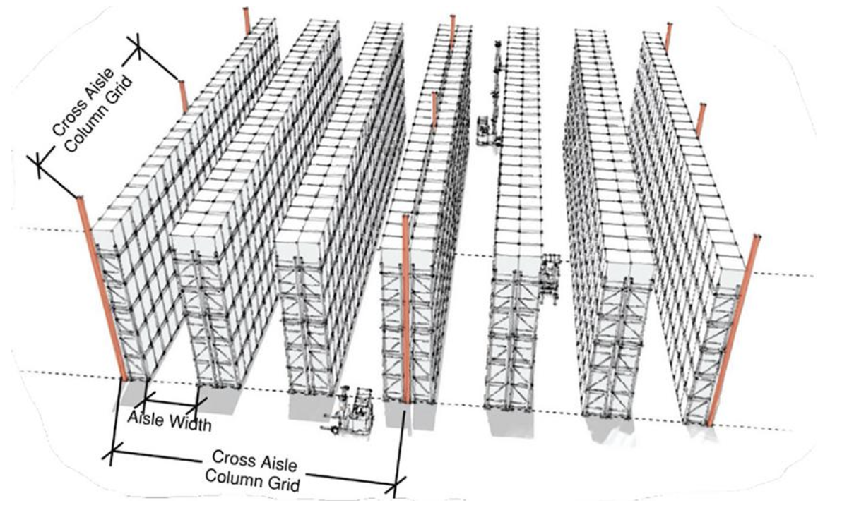
For an industrial warehouse facility, the main functionality is to store goods and materials, which are typically kept on small platforms called pallets. A typical pallet is 42 inches by 48 inches. They are either placed directly on slab-on-grade (SOG), which is called a bulk storage system or placed on metal rack systems, which is called a palletized racking system. Typically, palletized racking systems are the preferred approach for storing merchandise in distribution facilities. The typical down-aisle dimension (in the longitudinal direction) of these racks is 8 feet, and the cross-aisle dimension (in the transverse direction) is 4 feet. The racking frame is typically continuous in the longitudinal direction. It is commonly connected back-to-back with an adjacent frame in the transverse direction using a 6-inch coupler in the middle. This configuration is called a coupled rack system, which is very common in the industry. Figure 1 below shows a typical coupled rack geometry for a typical industrial warehouse.
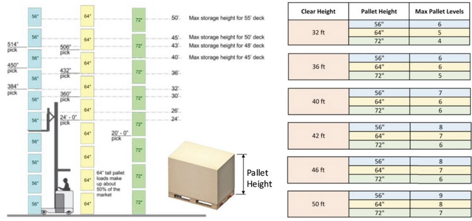
The vertical rack spacing and the number of levels within the rack are other important considerations of storage racks. The vertical spacing should accommodate the pallet height plus an 8-inch clearance between pallets and racking frames. The industry standard pallet heights for distribution facilities in the US are 56 inches, 64 inches, and 72 inches. The number of rack levels is greatly dependent on building clear height and pallet heights. The clear height is the height measured from the finished floor to the bottom of the lowest roof framing member. This is the maximum height that racking can extend vertically, and it directly defines the volumetric capacity of the facility. Within the clear height, the maximum number of rack levels can be determined [2]. Figure 2 presents the pallet utilization configuration for different building clear heights and different pallet heights.
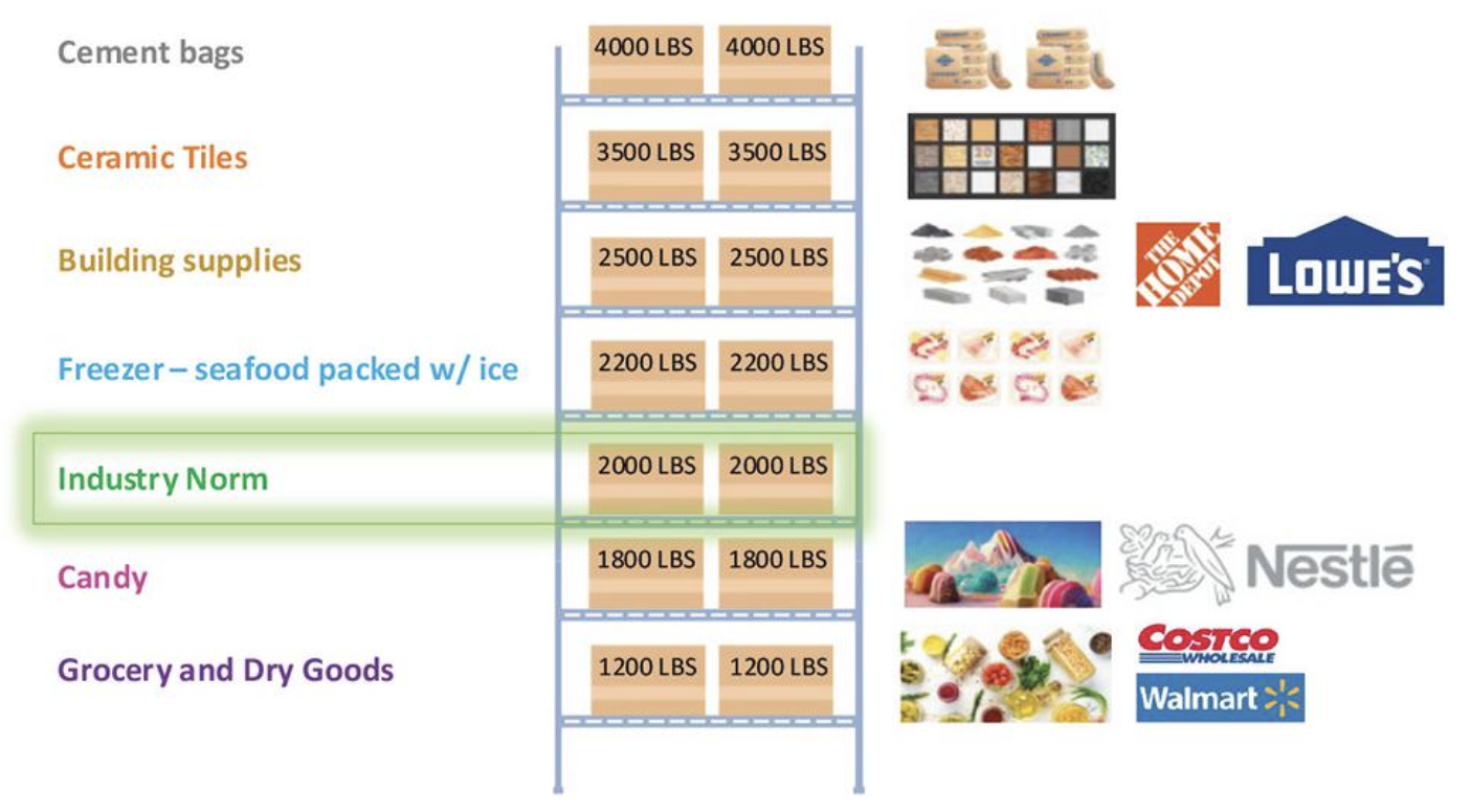
The weight of the pallet is highly dependent on the merchandise or material the pallet carries. Typical weights range from 1,000 to 4,000 pounds. For instance, pallets that store dry grocery goods, candies, and freezer items typically weigh 1,200, 1,800, and 2,200 pounds, respectively. Pallets that store construction materials such as building supplies, ceramic tiles, and cement bags typically weigh 2,500, 3,500, and 4,000 pounds, respectively. For an industrial building without an assigned tenant, the industry standard is to assume a pallet weight of 2,000 pounds. Figure 3 shows the pallet weight of each
category. These weights are critical for slab-on-grade design in that they directly dictate the amount of seismic load that is eventually transferred to the slab. Another important governing factor for seismic load to the slab is the seismicity of the site. The seismic load is directly proportional to the seismicity, and it is directly measured by the short-period spectral acceleration (SDS). This value can be found either through the ASCE 7-16 hazard tool or the geotechnical report.
Design of Slab-on-Grade
The racking system inside the building is directly supported by a slab-on-grade. Therefore, the slab should be designed to support all loads coming from the racking. Typically, two load effects mFs-lapust be considered during the design of the slab, namely, down push and uplift force coming from rack posts. Downward forces typically do not govern the design as the slab will be supported by the soil below, and an increase of the base plate dimension of rack columns would greatly help to increase the capacity to support gravity load. The uplift force, as a result of the seismic loads on the racking system, usually governs the slab design. During a seismic event, the lateral force imposed on the racking system will induce tension and compression coupled to the rack columns. After combined with gravity loads per the Racking Manufacturer Institute (RMI), net uplift would occur and can be determined. The net uplift force tends to pull the slab away from the soil support, and thus, it is the slab itself that provides resistance to the uplift. To quantify the net uplift, four pieces of information are critical, including the building clear height, the pallet weight, the pallet height, and the site seismicity.
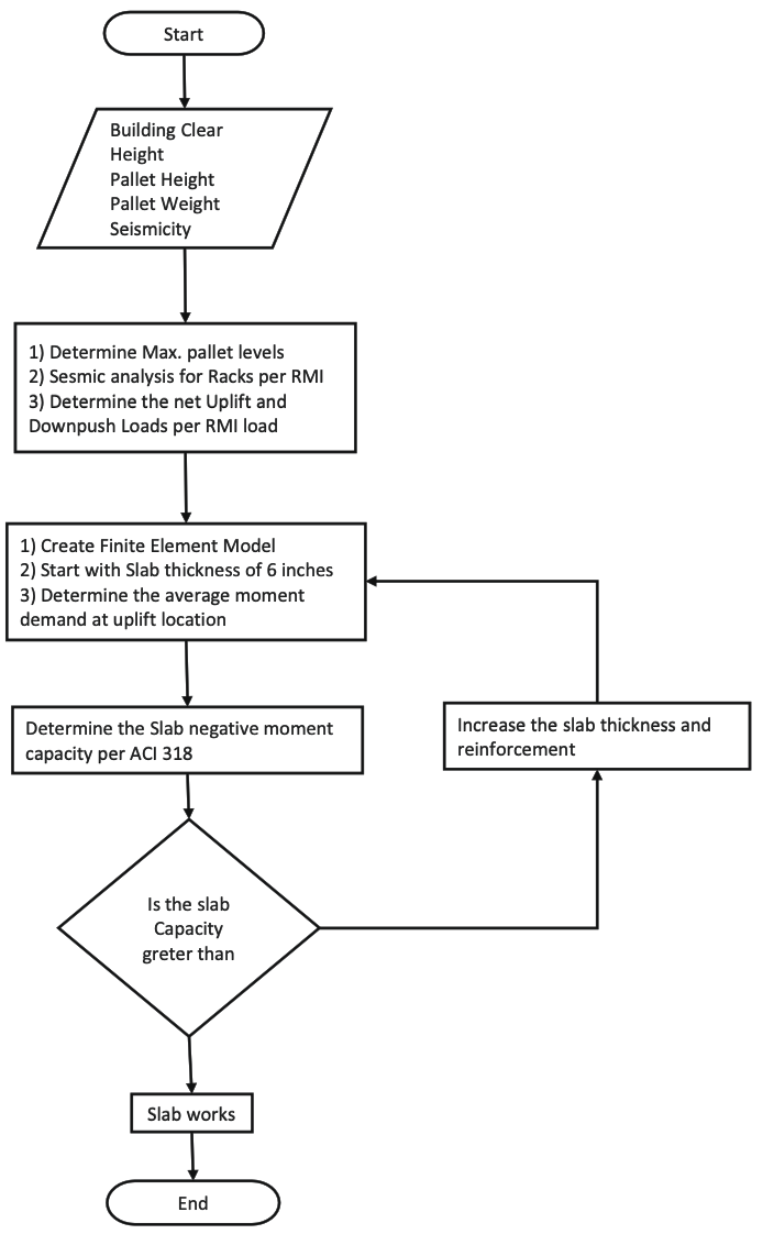
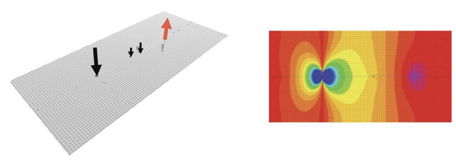
To evaluate the slab capacity subjected to uplift and down push forces, we follow the ow chart as shown in Figure 4 below. First of all, one needs to determine how many pallets will be utilized to maximize the logistic efficiency of the building based on the clear height. This can be accomplished using Figure 2. Then, the lateral load to each level of the racking system should be determined per the RMI guidelines, and its load effects should be combined with gravity load effects to determine the net uplift and down push force to the slab. e next step is to create a numerical model and analyze the slab subjected to downward and uplift forces. At this stage, one would start with an initial assumption of slab thickness. In this finite element analysis, slab-on-grade is typically modeled using shell elements, and the soil below should be modeled using nonlinear compression-only spring elements. After running the analysis, the maximum negative moment to the slab can be determined. Figure 5 shows a typical 3D view of the numerical model of the slab subjected to downward and net uplift, as well as the moment contour within the slab. The final step is to determine if the assumed slab thickness is able to provide the capacity to resist the uplift force. This is an iterative process until an adequate slab thickness is determined.
Slab-on-Grade Design Chart
Following the above-mentioned process, we performed a series of parametric studies of a slab for a typical industrial building with 40 feet clear height with combinations of different seismicity and slab thickness. The seismicity considered varies from 0.5g to 2.0g, and the slab thickness considered includes 6, 7, 8, 9, and 10 inches. It is assumed that the reinforcement is around 0.1% of the slab area and that concrete compressive strength is 3500psi. After obtaining a cluster data point in terms of Seismicity (SDS), slab thickness, and the corresponding pallet weight that the slab can support, a second-order regression analysis is then performed to generate contour lines and, thereby, a lookup chart as shown in Figure 6. In this figure, the horizontal axis is the seismicity (SDS), and the vertical axis is the pallet weight that can be accommodated by the slab. In addition, different line types represent different slab thickness, which is overlaid above each line type. This chart clearly shows that as seismicity increases, the maximum pallet weight the slab can accommodate decreases. For the same seismicity, an increase in slab thickness supports more pallet weight. More importantly, from this chart, one can quickly estimate the pallet weight the slab can support based on the seismicity and slab thickness without the need to go through the complete design and check process.
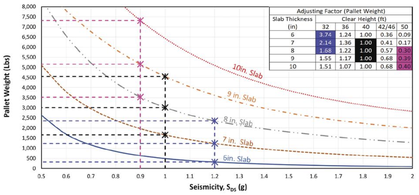
Furthermore, the study is extended to buildings with different clear heights, including 32, 36, 42, 46, and 50 feet. Instead of generating different lookup charts for buildings with different clear heights, we used the 40-feet clear building height results as the baseline case, and adjustment factors are determined by correlating the results for a building with different clear heights and baseline case results. is adjustment factor is summarized and provided in the table shown on the lookup chart. Now, utilizing the combined lookup chart and the adjustment table, one is able to very easily determine the maximum accommodated pallet weight considering a given seismicity and slab thickness for buildings with different clear heights.
Examples
- A 40-foot clear-height warehouse is located on a site with a seismicity of SDS = 1.0g; what is the recommended slab thickness? From the lookup chart, we can easily determine that an 8-inch slab is able to support a racking system with a pallet weight of 3,000 pounds. For 7 and 9-inch slabs, the maximum pallet weights are 1,600 and 4,500 pounds, respectively. Note that this chart is for a 40-foot clear building, and the adjusting factor is 1.0 in that case.
- A 32-foot clear building with seismicity of SDS =1.2g, what is the recommended slab thickness? From the chart, one can determine that 6, 7, and 8-inch slabs can support pallet weights of 400, 1,200, and 2,400 pounds, respectively. In addition, adjustment factors of 3.74, 2.14, and 1.68 should be applied. Therefore, 6, 7, and 8-inch slabs can support pallet weights of 1,496, 2,568, and 4,032 pounds, respectively. In this regard, a 7-inch slab is recommended to meet 2000lb pallet weight industry standards.
- A 50-foot clear building with seismicity of SDS =0.9g, what is the recommended slab thickness? From the chart, the pallet weight associated with 8, 9, and 10-inch slabs is 3,500, 5,100, and 7,300 pounds, respectively. In addition, adjusting factors of 0.30, 0.39, and 0.40 should be applied. Therefore, 8, 9, and 10-inch slabs can support pallet weights of 1,050, 1,989, and 2,920 pounds, respectively. Therefore, a 10-inch slab is recommended.
Conclusions
In the context of an industrial building, the design of a slab-on-grade holds the utmost importance due to its pivotal role in supporting anticipated loads imposed by rack supports. The design process, especially the selection of an optimal slab thickness, proves to be time consuming, primarily because it entails intricate numerical modeling. In this study, we conducted a systematic parametric analysis of slabs on grade for buildings with varying pallet weights, clear heights, and seismic conditions. We employed regression analysis to develop a convenient lookup chart, allowing for rapid estimation of the maximum pallet weight the slab can support based on its thickness and seismicity. Additionally, we created an adjustment table for buildings with different clear heights. This tool can greatly assist design teams and owners in making quick decisions, especially during the early stages of building planning, concerning the building’s functionality.
References
Boyd C. Ringo and Robert B. Anderson, “Designing Floor Slabs on Grade: step by step procedures, sample solutions, and commentary-second edition,” Aberdeen Group, Addison, Illinois, 1996.
ACI Committee 360 Report, “Design of Slabs-on-Grade,” 2010.
The Concrete Society, “TR34: Concrete Industrial Grade Floors – Fourth Edition”, 2013.
Wayne W. Walker and Jerry Holland, “Design of Unreinforced Slabs-on-Grade Made Easy” Concrete International 23.5 (2001), pp. 37-42.
Shentu, Longmei, Dahua Jiang and Cheng-Tzu Thomas Hsu, “Load-Carrying Capacity for Concrete Slabs on Grade,” Journal of Structural Engineering, ASCE, pp. 95-103, January 1997.
ANSI MH16.1, “Specification for the Design, Testing, and Utilization of Industrial Steel Storage Racks”, 2012.