
Considering the effects of ground movement on internal structural forces.
Many structural failures share one common theme: uneven ground settlement. As structural engineers are trained at a university, they assume that the “fixed base” of our buildings is FIXED. However, the effect of settlement on the above-ground structure can be dramatic. As a building sinks unevenly, moments and shears are redistributed to stiffer adjacent elements (columns, beams, walls, etc.) which add to their total load demand. Like a human being injured in one leg, weight is redistributed to the other leg, and a person’s center of gravity shifts and the body can become unstable, leading to their fall.
Consequently, a building will redistribute weight because of stiffness variation from the sinking columns, which adversely affects the other columns. Analysis of a simple moment frame confirmed that the bending moments would increase 20% to 35% for a 1-inch deflection, and deflections will dramatically increase to 3 to 4 inches at a single column line.
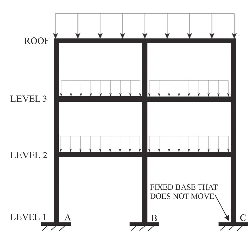
Let us start with a statement found in almost all of our college structural analysis textbooks: “All structures are stable and fixed/pinned at their base, with the foundation never moving.” Figure 1 illustrates a simple 3-story moment frame building with fixed base connections. Points A, B, and C are assumed to be level and never displace vertically or horizontally (small deflection theory). Our education in structural analysis, design, retrofit, codes, and basic theory is formulated on this critical assumption: the ground never moves, or if it does, the movement is too small to be of any significance.
Reality Check: The Ground Does Move
Over time, the support of a structure will change due to varying soil conditions, moisture levels, mild earthquakes, and possible landslide conditions. These factors are not part of our conventional wisdom as structural engineers because we are never taught that this may happen. It is completely outside of our envelope of expectation.
Examining our building codes, structural textbooks, and research efforts for the past 80 years shows that “we” [structural engineers] work from the premise that the building will not move. We establish our design practice using sophisticated analysis methods such as finite element analysis, dynamic analysis, and nonlinear analysis, all founded on stable foundations. Certainly, for many buildings and bridges, this has proven to be a good working methodology. Iconic structures like the Golden Gate Bridge (almost 90 years of service), the Empire State Building (90+ years of service), and the Taj Mahal (over 400 years) have lasted well beyond their expected lifespan and defied collapse through numerous natural events.
But recently, there have been structural failures that are baffling investigators and give a reason for the re-examination of our standard of practice stemming from ground movement. A recent landslide in Rancho Palos Verdes, California is a prime example of ground movement which no conventional structure could have survived. Many structural engineers would lay the blame on the geotechnical engineers and geologists and claim this is “not our fault.” Not true. Structural engineering is not just the “structure above ground” but includes the long-term stability of the foundation. We should be looking holistically at the entire system, not just “our part” above ground. We should remember that geotechnical engineers and engineering geologists provide information and data on soil conditions with recommendations to structural engineers for our design. They are not building design professionals; structural engineers are. Just like architects who perform their scope of design dealing with form, function, aesthetics, lighting, colors, shading, and the ethos of the structure, structural engineers have to take responsibility for our expertise and provide cautionary recommendations as necessary during the design phase.
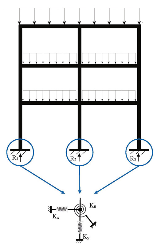
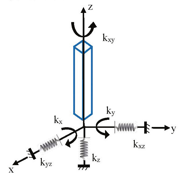
Therefore, Figure 1 from our structural textbooks is not reality but instead is more like Figure 2A. Each base support in two-dimensional space has three degrees of freedom (DOF) and can displace in two dimensions, plus rotate in-plane. Each DOF has a stiffness coefficient. Figure 2B illustrates three dimensions where the structure has six DOFs: three linear elastic springs and three rotational springs. The concept of multi-degree of freedom systems is usually part of graduate school structural engineering degree programs, but these principles are still usually introduced only for the understanding of the superstructure in conventional structural analysis, but not foundation movement.
For simplicity, we look at Figure 3A and examine the behavior as Ky degrades. When Ky degrades, see Figure 3B, the frame will deflect from Point B to B’, and the reactions will shift to Point A as the frame redistributes the vertical loads to the stiffer column.
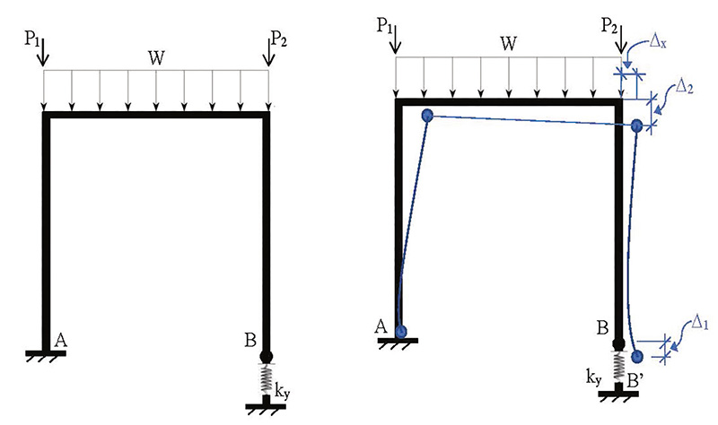
Figures 3a Single bay moment frame with one degree of freedom.
Figures 3b Single bay moment frame with one degree of freedom deflection plot.
This basic structural redistribution of loads is observed in Figure 4A for a simple beam. As the vertical stiffness of Point B degrades, see Figure 4B, the load reaction at Point A will increase. The vertical loads will shift to the remaining support point as the stiffness degrades at the other reaction point.
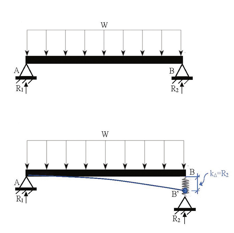
Figures 4b Simple beam with one degree of freedom base reaction.
Equilibrium is the fundamental equation that keeps every structure standing. The balance of the forces and moments is formulated from Newton’s Law. When one support loses its capacity to accept the vertical force demand, then that force (mass multiplied by the acceleration due to gravity) has to be transferred to other supports. It must go somewhere, and so the redistribution of the loads (and stresses) in the structure is automatic and follows the basic laws of physics. If we revisit our textbooks and recall the classical method of Moment Distribution (developed by Hardy Cross), this analysis method illustrates the re-distribution of moment to balance at the frame joints.
Practical Analysis
Geotechnical reports will give an estimated long-term settlement, often in the range of ½-inch to 1-inch for firm soils, over the life of the structure. This is an estimation based on the soil conditions at the time of completion of the construction of the building. Therein lies the basic fallacy: soil conditions can change over time. During design, we assume that the moisture content and bearing capacity will not change over time, but they can. For example, seepage from a leaking water main or in-ground swimming pool will certainly affect the soil parameters. Over-watering from irrigation will affect the soil capacity. Dewatering on adjacent construction sites can lower the water table. These factors are not included in a soils report because the geotechnical engineer is not expected to forecast them, but these factors do occur in reality.
These factors suggest the need for structural monitoring and capacity analysis over time, at least for structures where deterioration leading to failure would have consequences for the public. We cannot assume that “everything” will remain static over 50 to 100+ years. For example, Florida has instituted a timeline for structural monitoring and recertification of building occupancy on a 10-year schedule. New York City recently experienced a sudden collapse of a Manhattan parking structure and has instituted a similar law. California (and all other states) are considering similar measures, like California’s Balcony Law (Senate Bill 326), which requires structural examination every 6 to 9 years for wood balconies.
Portal Frame Analysis
For simplicity, this paper examines a single-bay portal frame. A portal frame is a snapshot of a larger multi-story moment frame system and illustrates these concepts with a basic analysis where one support sinks. Modeling this with a portal frame allows an engineer to analytically determine reaction results when ground movement occurs at one side of the frame. Degrading soil stiffness results in shifting load and moments in the superstructure. Let us take this principle and apply it to a basic building frame system, as shown in Figure 5.
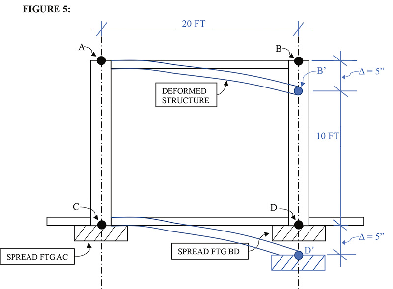
The dimensions were taken from the plans of a recently collapsed building and are for a one-story version of a garage structure. As Point D deflects downward, the deformed structure above shows the elastic curve and movement of Point B, with the assumption that Points A and C are stable for simplicity. In reality, we do not know if Point C is stable, but for this analysis, we will assume it is.
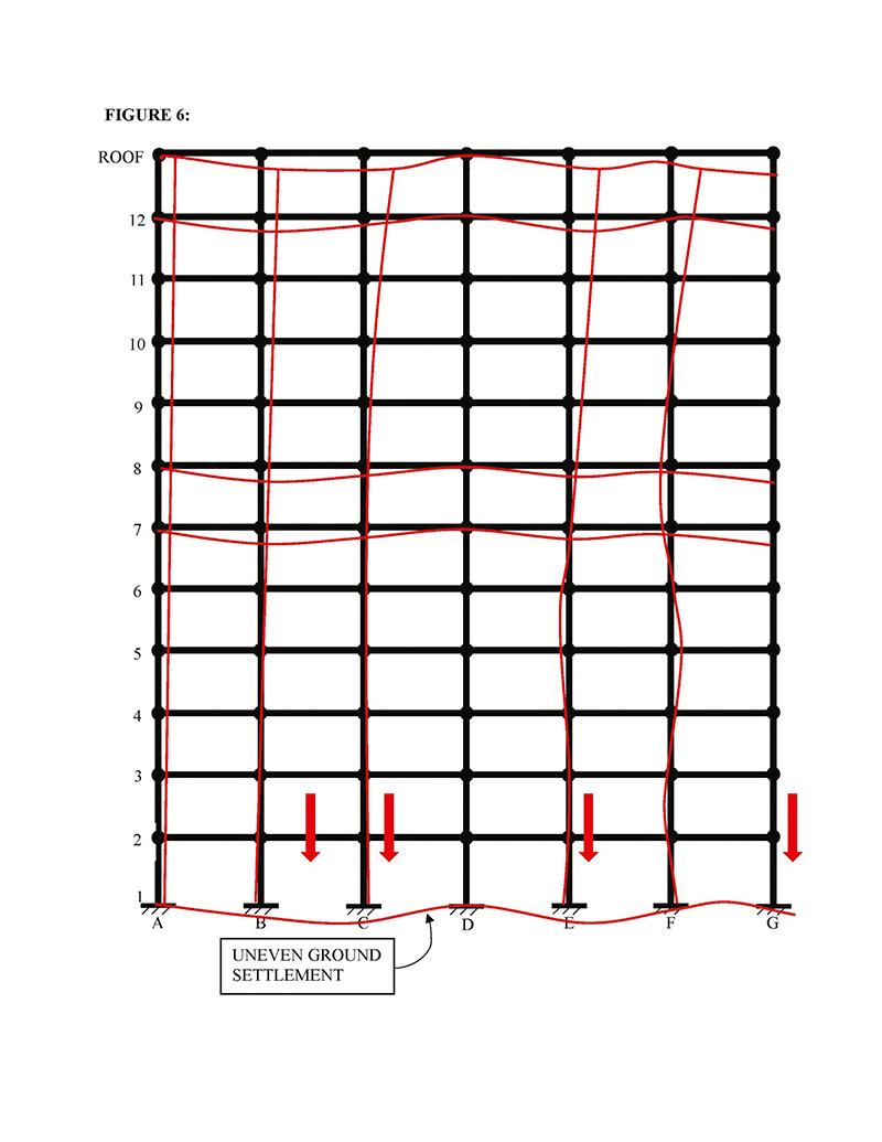
If we take this concept and extend it to a multi-story, multi-bay structure (see Figure 6), the analysis becomes more complex because of the variability in the ground movement.
Case Study Of Single Bay Moment Frame
Let us look at a single-bay frame taken from a recent collapse (see Figure 7), which has Cases A and B.
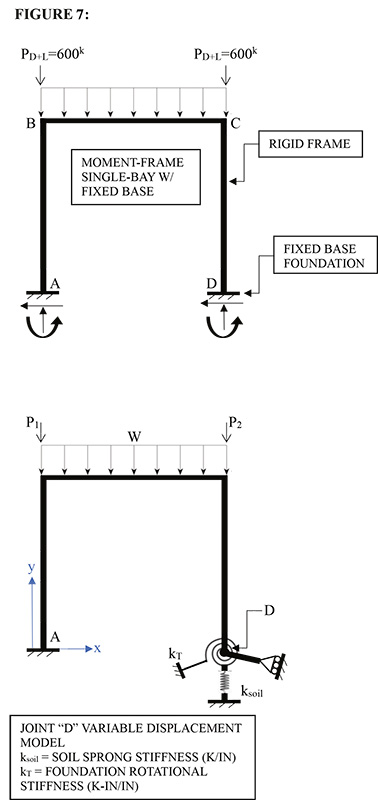
Case A: Conventional portal frame analysis with stable foundation support
Case B: Portal Frame analysis with degrading foundation stiffness at Point D
Case A provides a symmetrical moment diagram and is in many textbooks, so it is not presented here. Case B is shown with actual vertical loads from the building calculation but with no lateral loads.
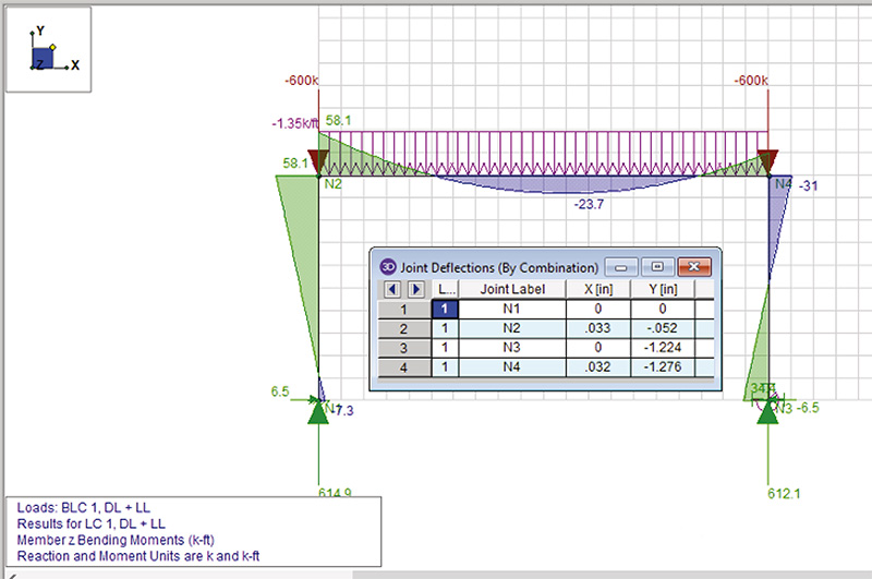
The moment redistribution and shifting of the reaction load is evident with a modest 1.28-inch deflection, see Figure 8. This affects and magnifies the moment values higher at Point A [N1] as Point D [N3] displaces further, and the moment at Joint B [N2] is increased. In principle, the structural theory is proven here that ground displacement will affect the moments, shears, and axial loads in the frame structure above. Similar conclusions will apply to other building types (i.e., shear wall structures, braced steel frames, concrete frames, wood frames, etc.).
Examples Of Structural Damage
From the textbook to the real world, we are now faced with physical evidence of structural cracking in columns and beams that may threaten the superstructure.
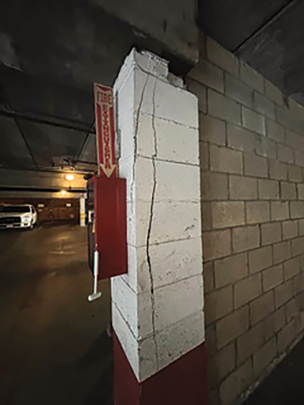
Figure 9 is such a case for a three-story complex with subterranean parking that has extensive cracking in column locations and is currently under citation.
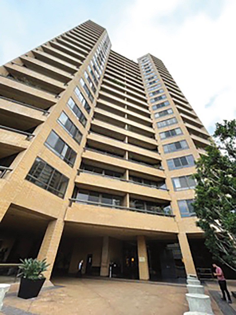
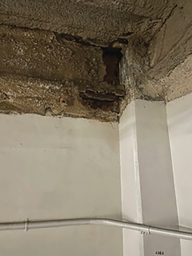
Figure 10 is a 22-story steel high-rise that has areas of water damage in the subterranean parking area, as shown in Figure 11. Examination of the structural connections is one part of the investigation. Structural engineers are also investigating whether ground displacement has led to asymmetric moment distributions and amplified stresses in the moment frame joints.
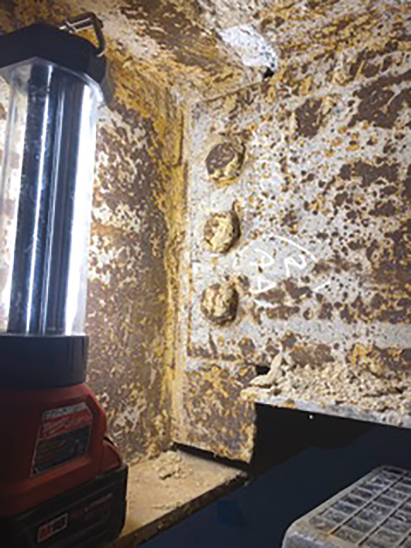
Figure 12 shows a beam connection with deterioration that passed testing, but this is not sufficient to conclude if the structure has displaced vertically. A physical survey should be part of the investigation process.
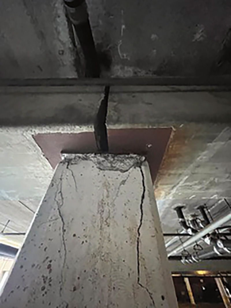
Figure 13 illustrates a potential column overstress that may be due to settlement and/or water damage.
Conclusions
The structural theory of stable foundations ought to be questioned based on recent and historical examples of settlement that have affected the structural distribution of loads. Structural engineers need to recognize these phenomena as potentially damaging, assess root causation, and address these concepts in standards, guidelines, and code provisions.
Our profession should take a proactive stance on this issue and call for research focused on this topic to upgrade and address our codes and standards. Our industry has an unfortunate “slow response” time to institute code changes. Still, we, as practicing structural engineers, should be examining our design practice based on practical analysis, not standards formulated by researchers and theoreticians.■
DISCLAIMER: The author, Dr. Khatri, is not part of any investigation team or research group funded by any entity. The examples cited here are for discussion only and do not suggest that these are established/proven conclusions for open cases. Dr. Khatri is a structural engineer with over 40 years of academic and professional experience and is not purporting to represent any structural opinions on open failure investigations, their designers, or causes of failure.