
Government (arsenal) bridge 1872
By 1870, the wooden Rock Island Bridge (Structure October 2022) needed replacement. The Federal Government decided to replace it with an iron structure crossing the land just south of the earlier bridge on the island’s west end. In May 1870, Major W. H. Benyaurd, the Army engineer placed in charge of the bridge, prepared a plan of the bridge site and located the position of the swing span close to Rock Island with an extensive set of specifications to be sent to prospective bidders. He wrote, “These specifications were general in their nature, and drawn up so that the bidders would have equal opportunities to compete for the bridge, no particular form of truss, nor any particular patent being specified, that would debar some firms from proposing, while at the same time, the Government would have the benefit of a greater number of plans to choose from, and be better enabled to secure a proper structure.” The specification was for an all-wrought iron structure and included the following:
The superstructure will consist of two spans of 260 feet, three spans of 220 feet, fixed in a permanent position, and one draw span, with two equal openings of 160 feet and a total length of 366 feet. Each span will consist of two trusses, 33 feet between centers of top and bottom chords, with wagon-road on bottom chords, and single-track railroad intermediate, allowing 12 feet headway for wagon-road. The trusses are to be placed 18 feet apart in the clear, with two sidewalks, each 5 feet wide, outside, on level with wagon-road and floor.
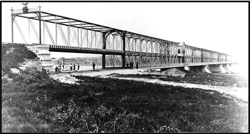
In other words, it would be a double-deck bridge with the roadway on the lower level and the railroad on the upper level. He sent the plans and specifications to many firms and got proposals from Kellogg, Clarke & Co., Phoenixville, Pennsylvania; Baltimore Bridge Company, Baltimore, Maryland; L. B. Boomer & Co., Chicago, Illinois; Keystone Bridge Company, Pittsburgh, Pennsylvania; and Detroit Bridge Company. Kellogg & Clarke, with the Detroit Bridge Company, had built the Quincy Bridge and Boomer, the first Rock Island Bridge; Keystone had also built the Keokuk and Hamilton Bridge. The only firm that had not built a bridge across the Mississippi was the Baltimore Bridge Company under C. Shaler Smith. Bids were opened in late October 1870 with Detroit Bridge & Iron Company as the low bidder and Kellogg, Clarke & Company as the highest bidder, with the contract going to Smith’s company. Benyaurd wrote:
The plans, &c., having been carefully considered, the award was made to the Baltimore Bridge Company, and a contract entered into on the 13th of October, 1870, for the draw-span, one span of 260 feet and one span of 220 feet, the amount of available funds on hand being only sufficient for these three spans, and current expenses, the remainder of the appropriation having reverted into the Treasury. The contract for the remaining spans over the main river, and the approach spans at each end, was not entered into until August 1871, after the money which had reverted into the Treasury had been re-appropriated.
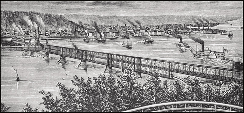
The bridge was not mentioned in the 1866 Federal Law governing bridges across the Mississippi and Missouri Rivers, but the requirements of that law were followed. The layout of the bridge starting on the Iowa or Davenport side and running easterly was as follows, a span of 196 feet, for railroad only, spans Second and Front streets, Davenport, these streets intersecting at this point. Then follow the double-deck spans across the river, in the following order: One of 260 feet; three of 220 feet each; one of 260 feet; draw span, 368 feet; finally, a railroad span of 100 feet, over the wagon road on the island, leading to the bridge, making a total length of bridge of 1,815 feet. This got the bridge to the Island.
Smith adopted Pratt Trusses for his single-level spans at the ends and Whipple double intersection trusses for his double-deck spans. For the double deck spans, “The trusses are 33 1/2 feet high between pin-centers, and placed 19 feet apart, allowing about 17 1/2 feet clear space. There are two floors: the upper, for the railroad, placed a little below the center of the trusses, and the wagon floor on the bottom chords. On each side of the bridge, outside of trusses, on a level with wagon road floor, are foot walks 6 feet wide, protected by substantial railing. About 12 feet clear headroom is allowed for wagons.” The verticals were built up with Phoenix sections fabricated with 4, 6, or 8 elements, with the smaller sections near mid-span and the large sections near the ends of the spans. The lower chords were wrought iron links, and the two-panel diagonals of iron bars were similar to but smaller than the lower chord members. “The top chord is 20 inches deep and from 22 inches to 24 inches wide, depending upon the panel’s position. Each segment is formed of four plates, 20 inches by 1 inch to 1 1/4 inches thick, connected together at top and bottom by 6-inch channel bars, filling-strips being also introduced between the channels and plates, in certain of the segments.”
Benyaurd wrote of the swing span, “The draw-span is a double Whipple, reversed-pin connections throughout. Each of the seven panels of the top chord, from the ends, is formed of two eye bars, each 9 inches by 1 1/8, to which eyes from 15 inches to 18 inches in diameter are welded; these eye bars form the outsides of the chord and are connected together by horizontal plates and diagonal strips, making each segment stiff, and from 20 inches to 24 inches wide, depending upon the position of the panel. The next four panels are made up merely of eye bars, from 9 inches by 1 1/4 to 9 inches by 1 inch, with eyes 18 1/2 inches, having respectively 4, 6, 8, and 10 bars in a panel. The remaining panel is a short one and used as a connecting link between the two arms; it is formed of four pieces, 18 1/2 inches by 1 inch, 5 feet long.” The swing span was built on the swing span island and was completed in mid-February 1872. The approach spans were then erected, and the main channel bridge was finished on May 1, 1872. Benyaurd had gotten the additional funding for the approach spans over the main channel. They were completed and tested on May 8, 1872, under a load of six flat cars loaded with sand weighing a total of 68,000#, and the deflections were never much over an inch.
Too much credit cannot be given to the Baltimore Bridge Company for the manner in which they performed their part of the contract and for the excellent workmanship and material that they put upon the bridge. And it is to be regretted that they were not so fortunate in a pecuniary point of view as they were in erecting the strongest and most perfectly finished bridge in America.
It was the longest, heaviest, and only double-deck swing span in the world at the time. The total weight of iron in the main channel spans was 6,675,000#, with a weight of iron and wood of 1,565,465# in the swing span alone. To move this great weight required a new mechanism that Smith developed to be powered by a steam engine mounted at the mid-span of the swing.
Bids for the spans over the easterly channel were asked for in November 1872 for “a through truss bridge 721 feet long in five equal spans; to have a roadway 20 feet in the clear and with two sidewalks each five feet in the clear; the roadway to be floored with oak plank 3 inches by 6 inches, and the sidewalks with pine plank, 3 inches by 6 inches, the latter to have a suitable hand-rail properly braced, the floor beams of wrought-iron, the floor joists to be of white pine.” Bids were opened in November 1872. The contract for these spans was awarded to Clarke, Reeves & Company, the successor firm to Kellogg and Clarke & Co., for $60,250. It was completed on July 1, 1873.
This bridge would survive until 1896 when Ralph Modjeski built the existing bridge on the original but reinforced piers.■