
Steel joists with flush framed end connections enhance floor vibration properties.
Recent floor vibration measurements and research completed by Vulcraft have shown that flush frame joist end connections can have a significant positive impact on a floor’s vibrational response when subjected to walking excitation. This article shows how the frequency and effective mass of the floor bay can be changed dramatically when switching from traditional bearing seats to flush frame connections developed by Vulcraft. Manual calculation procedures found in the American Institute of Steel Construction (AISC) Design Guide 11, 2nd Edition, Vibrations of Steel-Framed Structural Systems Due to Human Activity and the Steel Joist Institute’s (SJI) Technical Digest 5, Vibration of Steel Joist – Concrete Slab Floors (hereafter referred to AISC DG11 and SJI TD5) currently do not address steel joists with flush end connections. This article demonstrates how the provisions in AISC DG11 and SJI TD5 can be used for flush frame connections.
With traditional joist-bearing seats, the steel deck-supported concrete slab is above the top of the girder by the height of the seat, as shown in Figure 1(a). With flush frame joist connections, the slab is directly in contact with the girder, as shown in Figure 1(b).
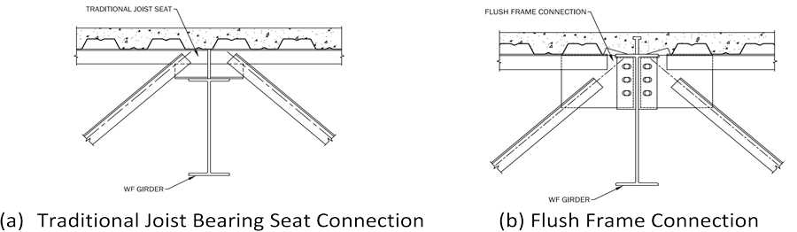
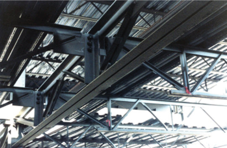
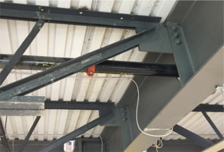
Figure 2 shows flush frame joist connections to a girder and a joist girder. With this type of connection, a vertical plate at the end of the joist is field bolted to a simple shear connection at the support.
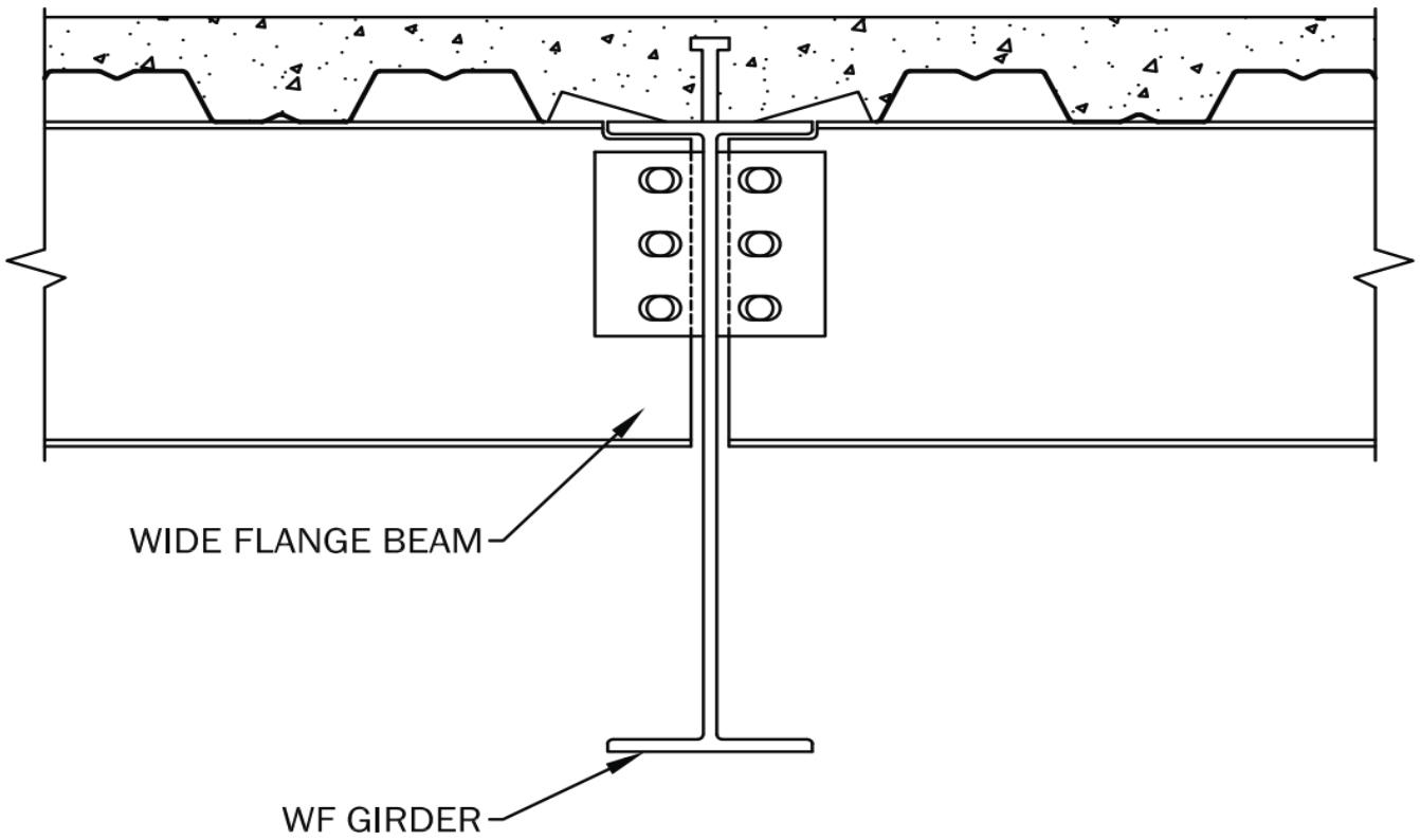
For a wide flange-to-girder connection, the concrete slab is also directly attached to the top flange of the girder, as shown in Figure 3. For these connections, whether the slab is connected using shear studs, ShearFlex® screws, or spot welds, the girder acts fully composite when subjected to walking excitation. AISC DG11 has guidance for predicting the natural frequency and effective weight associated with floor acceleration due to walking and rhythmic activities for these connections. When steel joists are fabricated with flush frame connections, the vibration behavior is similar to hot-rolled beams supported by hot-rolled or built-up girders.
The intent of this article is to 1) show the advantage of flush frame joist connections for controlling floor vibration caused by occupant activities and 2) provide the structural engineer with guidance for calculating the girder or joist girder natural frequency, fg, and effective joist panel weights, Wj, for flush frame-to-girder/joist girder connections using the AISC DG11 provisions.
AISC DG11 Provisions for Flush Frame Joist Connections
Following is an overview of how the applicable provisions for walking excitations contained within AISC DG11 apply to flush frame joist connections. Equations are referenced to AISC DG11.
Tolerance Criterion
The recommended criterion for low-frequency building floors is as follows: the floor system is satisfactory if the peak acceleration, ap, due to walking excitation as a fraction of the acceleration of gravity, g, determined from

does not exceed the tolerance acceleration limit, αo/g [0.005 (0.5%g) for offices or residences], where
P0 = amplitude of a 65-pound (lb.) driving force
fn = fundamental natural frequency of a beam or joist panel, a girder panel, or a combined panel, as applicable, Hertz (Hz)
β = damping ratio
W = effective weight supported by the beam or joist panel, girder panel, or combined panel, as applicable, lb.
Frequency
The girder or joist girder natural frequency is estimated using the fundamental natural frequency equation of a simply supported beam with a uniform mass:

where
fn = fundamental natural frequency, Hz
g = acceleration of gravity, 386 inch/second.2
∆ = mid-span deflection of the member relative to its supports due to the supported weight: that is,

where
Es = modulus of elasticity of steel, 29,000 kips per square inch (ksi)
It = transformed moment of inertia; effective transformed moment of inertia if shear deformation is included; reduced transformed moment of inertia to account for joist seat flexibility, in.4
w = uniformly distributed weight per unit length (actual, not design, dead and live loads) supported by the member, kip/in.
L = member span, in.
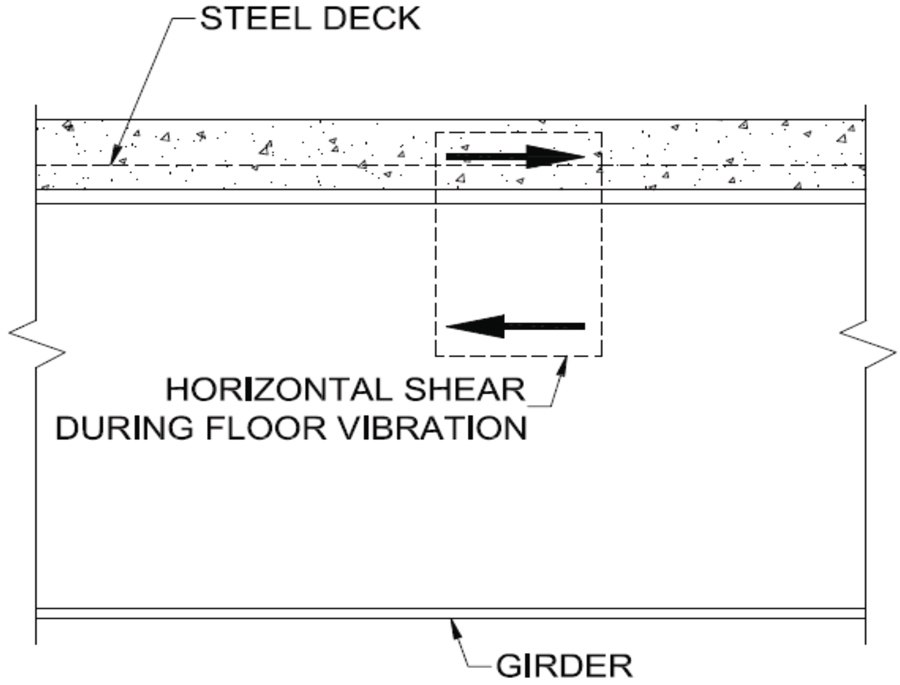
Human-induced loads typically cause mid-bay displacement amplitudes smaller than 0.01 in., implying very low horizontal shear force amplitudes (Figure 4) between the steel framing members and the slab. When the deck is in direct contact with the top of the member, deck fasteners, including spot welds and screws, provide enough slip resistance to ensure fully composite behavior. Members with physical separations between the member and the slab, e.g., a girder or joist girder supporting open-web steel joists with traditional seats, behave as partially composite members with an effective moment of inertia somewhat to significantly less than the full composite moment of inertia of the girder or joist girder.
The effective moment of inertia of joist girders supporting traditional joist seats is estimated using

where
Cr = coefficient from AISC DG11, 2nd Ed., Eqn. 3-9a
Ichords = moment of inertia of the chord areas, in.4
Ie = effective composite moment of inertia from AISC DG11, 2nd Ed., Eqn. (3-7), in.4

where
Ichords = moment of inertia of the chord areas alone, in.4
Icomp = fully composite transformed moment of inertia of the slab and chord areas, in.4
Similarly, the effective moment of inertia of hot-rolled or built-up girders supporting traditional joist seats is estimated using

where
Ix = moment of inertia of the girder, in.4
Icomp = fully composite transformed moment of inertia of the slab and girder areas, in.4
Effective Weight
The effective panel weight is estimated by determining the effective panel weights for the beam or joist panel (Wj) and girder panel (Wg) modes separately and then combining them in proportion to their flexibilities.
Where
Δj and Δg = mid-span deflections of the beam or joist and girder, respectively, due to the weight supported by the member, in.
Wj and Wg = effective panel weights from AISC DG11, 2nd Ed., Eqn. (4-2) for the beam or joist and girder panels, respectively, lb.
The effective panel weights for the beam or joist and girder panel modes are estimated from

where
w = supported weight per unit area, pounds per square foot (psf)
L = member span, feet (ft.)
B = effective panel width, ft.
For the beam or joist panel mode, the effective width is

where
Cj = 2.0 for joists or beams in most areas
= 1.0 for joists or beams parallel to a free edge (edge of balcony, mezzanine, or building edge if cladding is not connected)
Ds = slab transformed moment of inertia per unit width, in.4/ft
= approximately in.4/ft, or from a deck manufacturer’s catalog
de = effective depth of the concrete slab, taken as the depth of the concrete above the deck plus one-half the depth of the deck, in.
n = dynamic modular ratio
= Es/(1.35Ec)
Es = modulus of elasticity of steel, 29,000 ksi
Ec = modulus of elasticity of concrete, ksi
Dj = joist or beam transformed moment of inertia per unit width, Ij/S, in.4/ft
Ij = transformed or effective moment of inertia of the beam or joist, in.4
S = joist or beam spacing, ft
Lj = joist or beam span, ft
Floor width is the distance perpendicular to the span of the beams or joists in the bay under consideration over which the structural framing (beam or joist and girder size, spacing, length, etc.) is identical or nearly identical in adjacent bays.
For the girder panel mode, the effective width, except for edge girders, is

where
Cg = 1.6 for girders supporting joists connected to the girder flange with traditional joist seats
= 1.8 for girders supporting joists or beams connected to the girder web
Dg = girder transformed moment of inertia per unit width, in.4/ft
= Ig divided by the average span of the supported beams or joists, in.4/ft
Ig = effective transformed moment of inertia of the girder
Lg = girder span, ft
Floor length is the distance perpendicular to the span of the girders in the bay under consideration over which the structural framing (beam or joist and girder size, spacing, length, etc.) is identical or nearly identical in adjacent bays.
Where beams or joists are continuous at their supports and an adjacent span is greater than 0.7 times the span under consideration, the effective panel weight, Wj, can be increased by 50%. This liberalization also applies to rolled sections shear-connected to girder webs but not to joists connected only at their top chord with traditional bearing seats.
Beam to Girder Web Connection
The beam-to-girder web connection, shown in Figure 3, is a basic connection in AISC DG11. For this connection:
The girder is considered to be fully composite because the deck-to-girder top flange connection at the steel deck-to-top beam flange interface provides adequate resistance to the vibration-generated horizontal shear force shown in Figure 4. The connection can be spot welds, Vulcraft’s Ecospan ShearFlex® screws, or standard welded steel shear studs.
Cg = 1.8 when determining the girder panel mode effective width using AISC DG11 Eqn. 4-4.
If an adjacent beam or joist span is greater than 0.7 times the span, then the effective joist panel weight, Wj, from AISC DG11 Eqn. (4-2) can be increased by 50%.
Traditional Bearing Seat Connection of Steel Joists to a Girder or Joist Girder
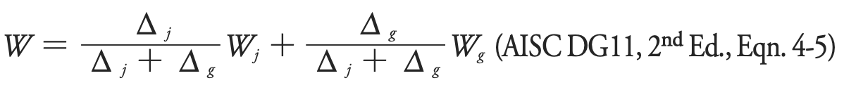
The traditional bearing seat on a steel joist is fabricated utilizing two clip angles attached to the double-angle joist top chord, as shown in Figures 1(a) and 5(a). The traditional bearing seat provides less horizontal shear continuity than if the slab was directly connected to the girder top flange, as shown in Figure 5, so the fully composite transformed girder moment of inertia does not apply. Also, because the traditional joist-bearing seat does not transfer joist end moments across the girder, there is assumed to be no participation of the mass of adjacent bays in resisting walker-induced vibration.
Thus, for this connection:
- The separation of the concrete slab and the girder top flange or joist girder top chord results in partial composite action, and the moment of inertia of the girder or joist girder supporting joist seats is determined using AISC DG11 Eqn. 3.11 or Eqn. 3.10, respectively. The primary result is a reduction in the natural frequency of the girder mode.
- The reduced connection stiffness requires that the coefficient Cg = 1.8 in AISC DG11 Eqn. 4-4 be reduced to 1.6 when traditional joist seats are used, resulting in a slight reduction in the girder mode effective weight, Wg.
- The non-participation of mass in adjacent bays means that an increase in effective joist panel weight, Wj, is not considered; that is, the 50% increase in joist panel weight, as recommended for shear-connected beam-to-girder connections in AISC DG11 Section 4.1.2, is not applicable.
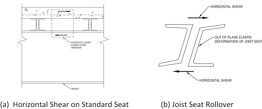
Flush Frame Joist Connection-to-Girder or Joist Girder
The flush frame joist-to-girder and joist-girder connections shown in Figure 2 are equivalent to the typical beam-to-girder web connection shown in Figure 3.
For these connections, the following apply and are illustrated in Figure 6.
- A hot-rolled or built-up girder is considered to be fully composite. A joist girder has the effective moment of inertia computed using AISC DG11 Eqn. 3-7.
- Cg = 1.8 when determining the girder panel mode effective width using AISC DG11 Eqn. 4-4.
- If an adjacent joist span is greater than 0.7 times the joist span, the effective joist panel weight Wj from AISC DG11 Eqn. 4-2 can be increased by 50%.
Wj = 1.5wjBjLj
Vulcraft Sponsored Testing
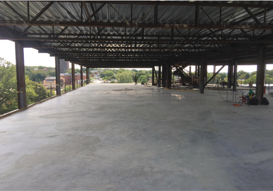
Vulcraft sponsored a testing program to investigate the vibration performance of a composite joist floor system with flush frame composite joist connections. At the time of the testing, the building shown in Figure 7 was under construction. The tested floors supported no superimposed mass and were in the bare slab condition, as shown in the photograph. The purpose of the testing was to experimentally determine the dynamic properties of the floors and vibration response due to walking for comparison with finite element analysis and AISC DG11 manual calculation prediction methods.
The finite element analysis method accurately predicted the responsive natural frequencies and mode shapes in the tested bays. On average, the predicted natural frequencies were 5% higher than measured. The AISC DG11 manual method predicted natural frequencies were, on average, 10% higher than measured.
Accelerations due to walking were measured in three bays. Even though the floor was in the bare slab condition without nonstructural components that add damping and mass, the vast majority of accelerations were far below the recommended tolerance limit for quiet office spaces.
The tested bays were highly resistant to walking-induced vibrations and performed well in service. This Vulcraft-sponsored testing program showed that the acceleration prediction methods used in AISC DG11 could be confidently used for vibration analysis of composite joists with flush frame joist connections.
Example: Standard Joist Seats vs. Joist Flush Frame Connections and Hot-Rolled Beam Framing Connections
The primary objective of this example is to show the effect on floor vibration response when flush frame joist connections are used for LH-series and CJ-series joists. A second objective is to show how a floor with flush frame connected joists compares to one with hot rolled members.
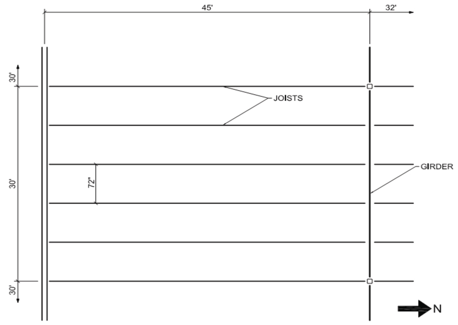
The exterior bay framing in Figure 8 is evaluated for vibrations due to walking in a modern (electronic) office. The building has joist spans of 45 feet-32 feet-45 feet and girder spans of 30 feet. The joist spacing is 72 inches. There are cold-formed steel walls above and below the spandrel girders. The exterior cladding is connected to the girders as well. Therefore, the spandrel girders are considered to be equivalent to exterior walls (infinitely stiff in the vertical direction) for vibration analysis. The floor slab has a total concrete depth of 5-1/2 inches, 2-inch deep composite deck, and normal weight concrete with f ′c = 3.50 ksi.
The 45 ft bays have a superimposed dead load of 15 pounds per square foot (psf ) and a design live load of 50 psf (reduced to 45 psf for the secondary members). The resulting design dead plus live load, not including the weight of the secondary member itself or any bridging, is 696 pounds per linear foot (plf). The loads for the 32-foot bay are 15 psf superimposed dead load and 100 psf live load.
The secondary joist and hot-rolled members shown in Table 1 satisfy strength and live load deflection requirements. The secondary joists with bearing seat connections are 28LH724/270 (required ASD 724 plf total load and 270 plf live load) joists and 28CJ716/270 joists. The secondary joists with flush frame connections are 28LH725/270 and 28CJ717/270. Note, from Table 1, the total loads shown in the joist designation include the weight of the joist. The non-composite interior girders are W27×84 sections, and the composite girders are W24×55 sections. For comparison with hot-rolled framing, the bay was analyzed for W18×35 composite beams and W24×55 composite girders.
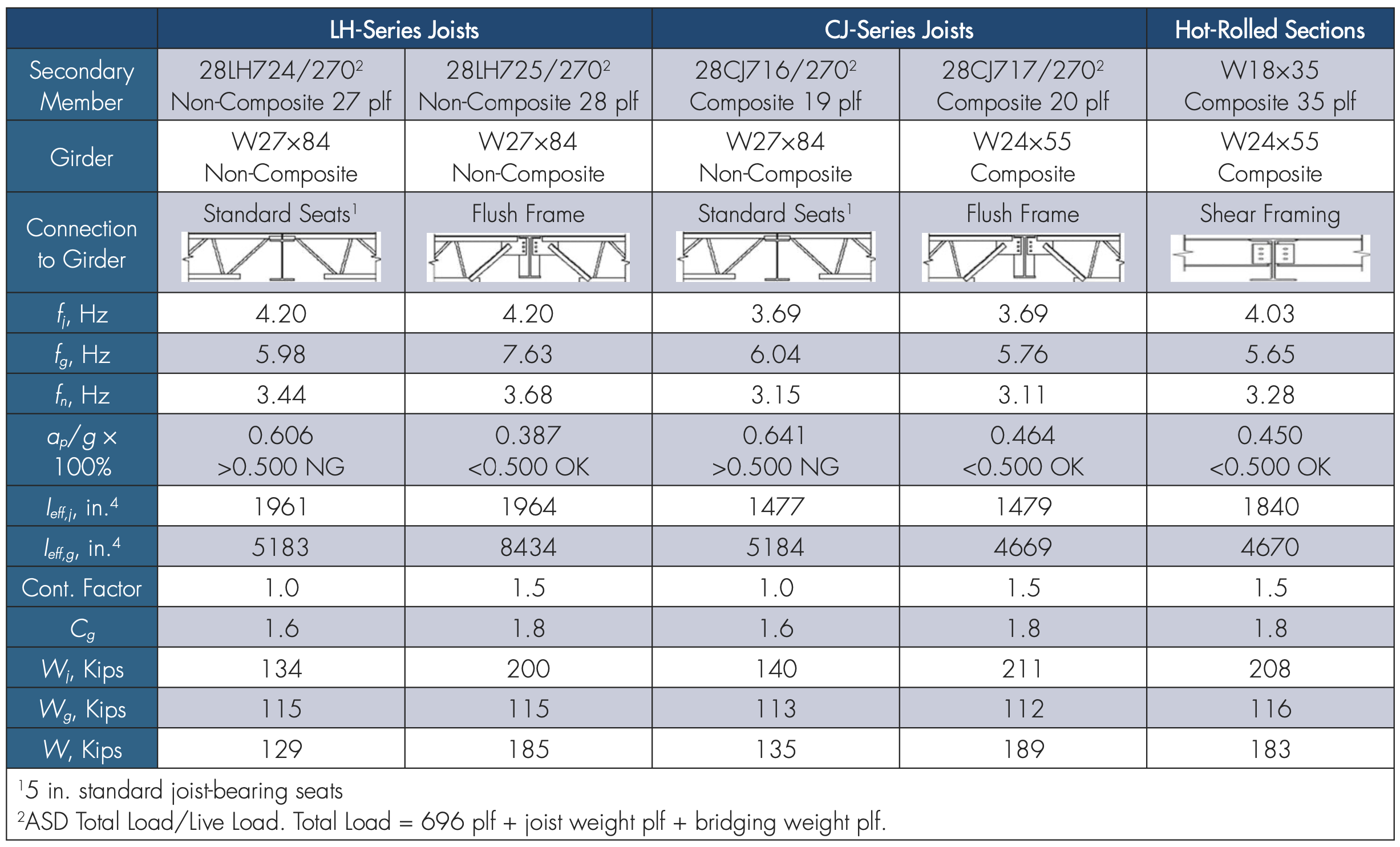
Vibration response analyses of the bay with LH- series and CJ-series joists with standard seats, and flush frame connections, and hot-rolled framing, were conducted. For the vibration analyses, the live load is 8.0 psf, and the superimposed dead load is 4.0 psf (ceiling plus ductwork per DG11 Section 3.3). The secondary member and girder effective moments of inertia, Ieff , are per the “AISC DG11 Provisions” section above. The assumed damping ratio is 0.025, as recommended in AISC DG11 for electric office fit-out with ceiling and ductwork below. The results of the five analyses are summarized in Table 1. (The software FloorVibe v3.1, floorvibe.com, was used to generate the analysis results.)
28LH Joists and W27×84 Non-Composite Framing, Standard Bearing Seats vs. Flush Frame Connections
The predicted frequencies and acceleration ratio for the bay framing with 28LH724/270 and 5-inch deep standard joist seats are joist frequency 4.20 Hz; girder frequency 5.98 Hz; bay frequency 3.44 Hz, and acceleration ratio, ap/g times 100% = 0.606% (0.606%g). The recommended tolerance limit in AISC DG11 is 0.50%g which is less than the predicted acceleration ratio and therefore is not an acceptable design.
For the same framing, but with flush frame connections, the frequencies are 4.20 Hz, 7.63 Hz, and 3.68 Hz, and the acceleration ratio of 0.387%g, which is less than the AISC DG11 limit and is an acceptable design. The reduction in the predicted acceleration with the use of flush frame connections is because of (1) an increase in the effective girder moment of inertia, Ieff ,g ,( 5183 in.4 to 8434 in.4), which in turn results in an increase in bay frequency (3.44 Hz to 3.68 Hz), and (2) an increase in the Continuity Factor from 1.0 to 1.5, which results in a significant increase of the effective weight, (129 kips to 185 kips), as shown in Table 1.
Note: If the girders supporting the flush frame connected joists are composite, the predicted acceleration ratio with W24x55 composite girders is 0.452% – a satisfactory result.
28CJ Joists, Standard Seats vs. Flush Frame Connections
As shown in Table 1, the predicted acceleration decreases from 0.641%g to 0.464%g < 0.500%g when 28CJ joist end connections are changed from 5 in. standard joist seats to flush frame connections. The causes of the reduction are the same as explained for the 28LH joists and W27×84 non-composite framing – see Table 1 for related values.
Hot Rolled Framing
The predicted frequencies and acceleration ratio for the bay framing hot-rolled beams and girders are a beam frequency of 4.03 Hz; a girder frequency of 5.65 Hz; a bay frequency of 3.28 Hz, an acceleration of 0.450%g < 0.500%g. It is noted that the secondary member weight, 35 plf, is significantly larger than for the joist secondary members.
Summary
AISC DG11 and SJI TD5 provide guidance for predicting the natural frequency and effective panel weight for traditional steel joist seats supported by hot-rolled and built-up girders or joist girders. This article provides recommendations for determining the floor’s natural frequency and effective panel weight when steel joists with flush frame joist connections are utilized.
With flush frame steel joist connections, the steel deck-supported concrete slab is in direct contact with the top of the girder. This results in the girder acting fully composite, as with hot-rolled beams framed into the web of a hot-rolled or built-up girder. Given the rotational restraint at the girder provided by the steel joist flush frame connections, vibrational energy is transferred across the girder over into the adjacent bay, increasing the slab effective weight by 50%, which in turn reduces the predicted acceleration ratio, ap/g, a significant benefit of the flush frame joist connection.
Utilizing flush frame joist connections, as opposed to increasing the concrete slab mass or steel joist depth to meet floor vibration requirements, can reduce the overall cost of the building. In areas where seismic forces can govern a building design, decreasing the concrete floor slab weights can reduce the seismic loads to that floor along with reducing the resulting foundation loads.■
References
Davis, D.B., (2022), Vulcraft Vibration Research, Composite Joists with Flush Framed Connections, 1785 Columbus Avenue, Boston, MA, Davis Structural Engineering, LLC, Lexington, Kentucky.
FloorVibe v3.1, floorvibe.com, Structural Engineers, Inc., Radford, Virginia.
Murray, T.M., Allen, D.E., Ungar, E.E., and Davis, D.B., (2016), Vibrations of Steel-Framed Structural Systems Due to Human Activity, Second Edition, Steel Design Guide Series 11, AISC, Chicago, Illinois.
Murray, T.M. and Davis, D.B., (2015), Vibration Analysis of Steel Joist-Concrete Floor Systems, Second Edition, Technical Digest 5, Steel Joist Institute, Florence, South Carolina.