
The completion of a 5-story mass timber commercial office building named Terminus in the city of Langford, British Columbia, on Canada’s west coast, marks an exciting first in the world of seismic systems for timber structures. The building includes 4 stories of post-and-beam mass timber with Douglas Fir glulam beams and columns and Spruce-Pine-Fir (SPF) cross-laminated timber (CLT), all supplied by Structurlam. While the structure and its detailing are clean, elegant, and modern, what is truly unique about Terminus is its steel-timber hybrid seismic force resisting system (SFRS).
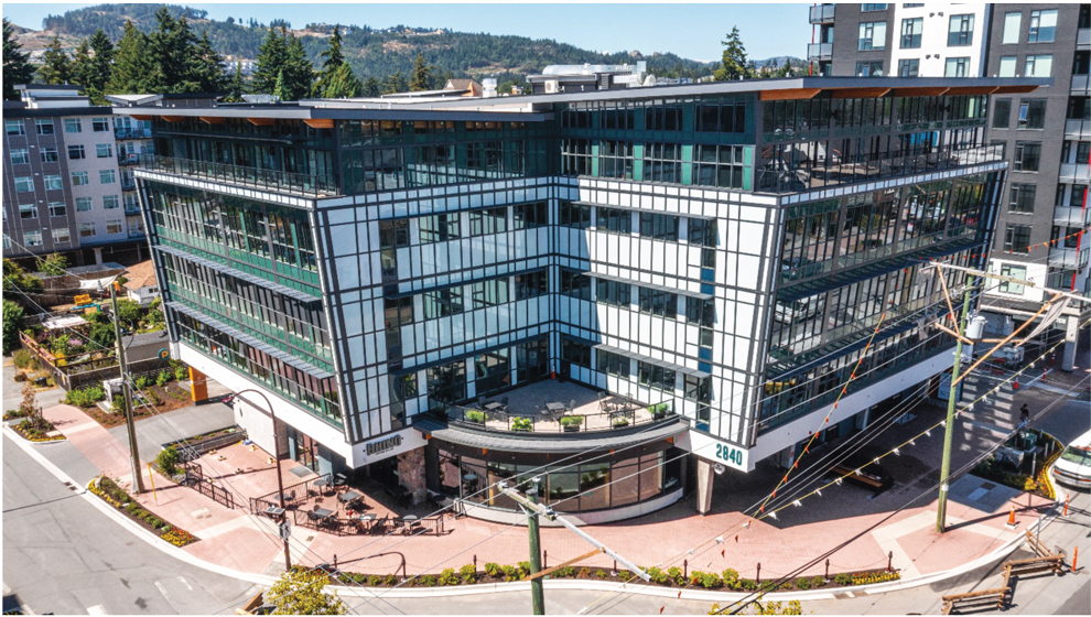
Terminus was developed to house the head office of Design Build Services (DBS), the building’s owner and the design-builder behind many Langford developments. As an early adopter of mass timber, DBS embraced the material fully, recognizing its innate benefits like the potential for fast speed of construction, low structural embodied carbon, and a beautiful, finished look. For Terminus, DBS sought out a building that had the architectural polish of modern mass timber without defaulting to a steel or concrete SFRS. The site is one of the highest-seismic regions of Canada; with significant lateral demands on the project, the lateral load-resisting system was a critical element of the building design. Aspect Structural Engineers, familiar with a large assortment of options for mass timber lateral systems, and with a mandate to spend the time and effort to make the right choice for the project, undertook a deep dive into investigating SFRS options that were high-performing, complementary to the exposed timber structure, and cost competitive.
Glulam Chevron Braces
One of the simplest mass timber SFRS options is glulam braced frames, which are permitted in the National Building Code of Canada (NBCC) with a combined RdRo factor of either 2 or 3, depending on the ductility of the detailing. RdRo is approximately equivalent to the Seismic Response Modification factor, R in ASCE 7, and fulfils the same function.
Neither the NBCC nor the Canadian timber code, Engineering Design in Wood (CAN/CSA-O86), include specific detailing provisions for timber braced frames, and it is left to engineering judgement by experienced engineers to demonstrate through research, testing, and project precedents that the system is adequately ductile. Best practices, research, and precedents indicate that the timber elements shall remain elastic and largely damage-free in a seismic event, while the connections between members (typically steel elements) provide the system’s ductility. As in many other seismic systems, steel elements that can undergo substantial and predictable plastic deformation without failure make good options for connectors in mass timber braces.
Tight-fit pin connections, with many small diameter pins that are tightly fit into the timber member and steel knife plate, can ensure a yield mode with bending of the pins and some wood crushing rather than splitting or fracture of the timber as long as limits are imposed on the pin spacing and slenderness. Tight-fit pin connections have been shown to provide adequate ductility for an RdRo of 2 or 3, however, this is still a relatively low response modification factor relative to other SFRSs and would make for a very high seismic demand building-wide. A low RdRo factor can also drive up elements that are capacity protected (designed to exceed the expected capacity of the SFRS), including timber member sizes, foundations, and the diaphragm.
Slip Friction Damper
Intrigued by slip friction dampers supplied by Quaketek, a Quebec-based manufacturer, and their capacity to dissipate a large amount of seismic energy, the team investigated their use for the Terminus project. Instead of damping and energy dissipation stemming from the yielding of steel elements, these dampers function by clamping steel plates together and providing damping via the friction generated when the plates slide past one another. A major advantage of these devices is that there is no sacrificial structural component; energy is dissipated via friction instead of steel yielding. These are typically used in steel and concrete structures, both in seismic retrofits and new construction. There is research demonstrating that the use of these dampers provides a hysteretic performance approximately on par with Buckling Restrained Braces (BRBs), providing a pathway to an equivalent response modification factor.
One disadvantage of these dampers is the lack of self-centering capability of the system. Because the dampers use friction to dissipate energy, there is no elastic component to the deformation that can pull the system back to center once the slip friction is exceeded. Combining slip-friction braces with elastic supplementary moment frames is often recommended to provide nominal elastic centering to the building. Mass timber moment frames are not unattainable, however in analyzing the building and determining the stiffness that would be required for the moment frames to be effective, it was clear that the mass timber elements within the moment frames would need to be significantly upsized, increasing the overall project cost.
Tectonus Resilient Slip Friction Joints (RSFJ)
Tectonus RSFJs are devices that have been developed for timber structures in for high-seismic regions. This system was invented in New Zealand in the aftermath of the 2010 Christchurch earthquake and the resulting catastrophic damage that occurred. RSFJs are spring-loaded slip friction dampers, so there is a built-in self-centering component to the system. Rather than reduce the building’s base shear via energy dissipation due to friction alone, these devices produce a flag-shaped hysteresis, reducing the building’s base shear by providing energy dissipation and by increasing the period of the building while ensuring that the drift limit is maintained. The RSFJs can result in a building with less post-earthquake residual deformation than typical non-centering systems.
Because the period shift is critical to the design and performance of the RSFJ, the analysis should be completed using a deformation-based approach instead of an equivalent static or linear dynamic analysis that is more typical of Canadian and US seismic design. ASCE 41 is an excellent resource for performance-based design of lateral systems that do not have an established response modification factor; the performance level (drift limits, in this case) is established first, and the device is tuned to achieve those limits with adequate damping in order to limit the force demands.
Buckling Restrained Braces (BRBs)
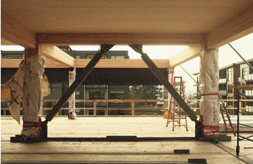
BRBs are steel braces that have a yielding steel core that is restrained from buckling by a grout-filled outer steel casing. These braces are increasingly used in mass timber structures in high-seismic regions due to the well-established code procedures for design and testing, and the high response modification factor (RdRo = 4.8 in Canada and R = 8 in the United States). In a mass timber building, BRBs will typically necessitate steel columns and beams at each braced bay to fully comply with prescriptive code requirements.
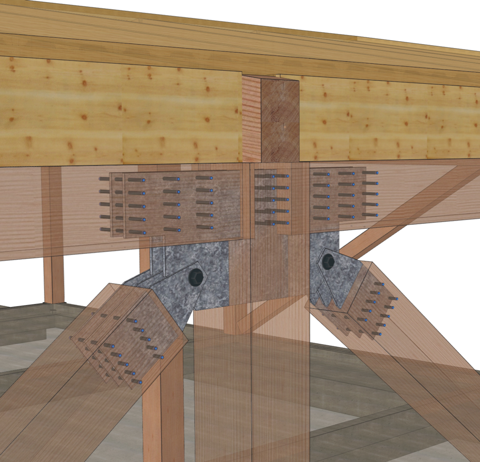
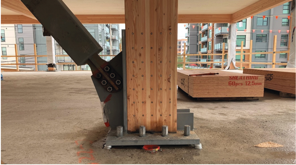
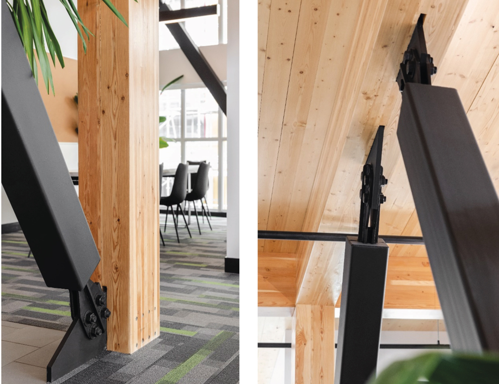
Since the client was interested in the appearance of the mass timber structure and keeping as much of it exposed as possible, a novel approach to BRBs was developed for this project: using BRB braces within an all-timber frame instead of substituting the glulam columns and beams for steel within the braced bays. Finding no precedents for this approach, the team looked to first principles, the intent behind the BRB Canadian code provisions, and timber best practices to ensure compatibility between the timber and steel elements and maintain overall performance of the BRB braced bays.
Making the Choice
In the end, the friction damper and the glulam brace options were both eliminated early in the study. Glulam braces did not have a high enough response modification factor to suit the project’s high seismic demand, and given the preferred brace layout, this system would have driven up the cost of timber members, diaphragm detailing, and foundation design. Slip friction dampers were likewise eliminated once the perimeter moment frames were sized and found to be too costly and having too much architectural impact due to the larger members. With roughly comparable performances for both the BRB and the Tectonus RSFJ options, the decision came down to the cost of the systems. Ultimately, BRBs by Corebrace housed within a mass timber frame were selected as the building’s lateral system.
Design Approach to BRBs in a Timber Frame
The design approach started with the BRB system detailing requirements included in the Canadian steel code (CSA-S16), many of which are similar to the requirements in AISC 341. Some of the code provisions are listed below:
- The BRB elements shall be able to resist, without buckling, the forces and deformations that develop in the brace at 2.0 times the seismic design story drift.
- The probable tensile and compressive resistances of the bracing members shall account for strain hardening (tension and compression) and friction (compression only) via adjustment factors.
- The resistance of brace connections shall equal or exceed the probable tensile and compressive resistances of bracing members.
- The resistance of beams, columns, and all connections other than brace connections shall equal or exceed the effect of gravity forces and the probable tensile and compressive resistances of bracing members.
- Columns in multi-story buildings shall be continuous over a minimum of 2 stories.
In addition to this code guidance, adding the following provisions to the timber detailing approach justified that the performance would be comparable to an all-steel system: - Ensure deformation compatibility can be achieved by minimizing rotational restraint at beam-to-column connections to avoid the timber frame behaving as a moment frame. Aligning work points, slotting steel elements, and using small-diameter connectors (see item “g”) all helped to achieve this critical rotational release.
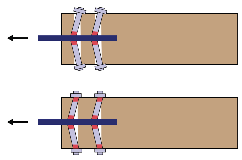
- Maintain ductile timber connections via many small-diameter, tight-fit pins and tight-fit bolts, even though the timber connections were not designed to yield or dissipate energy. Doing so better allowed the team to establish the deformation compatibility identified above.
- Introduce a steel tie member at the braced frame beam to minimize steel-to-timber connections at the top of each chevron, as shown previous page on the bottom left. A raised access floor above the CLT deck allowed this steel tie, as well as all steel collectors, to remain hidden.
While the design strategy was based on solid engineering principles and an understanding of timber mechanics, the Terminus team was then pleasantly surprised to learn that this approach was independently verified by research in New Zealand that was underway shortly before construction of Terminus began. A PhD candidate at the University of Canterbury, Wenchen Dong, tested the performance of BRB braces in mass timber frames with different connection approaches and published his PhD thesis in 2021. He found that the best connection performance came from tight fit pin connections, which demonstrated moment release and did not restrict frame rotation.
Getting it Built
Most of the SFRS options considered above are not codified and needed to be submitted to the AHJ as a code alternate. Working closely with the City of Langford’s building department early in the design process allowed the team to identify and address their requirements for approving the system. In general, early engagement with the AHJ is ideal for introducing new concepts and code alternates and allowing them time to learn, ask questions, and provide the pathway for approval. On the Terminus project, the AHJ was satisfied that the detailing approach for the BRBs was adequate to allow the BRBs to be used with the full response modification factor without penalty.
The early work on design and analysis paid off with a very smooth construction period. To compress the schedule, the mass timber connection detailing was completed in parallel to the mass timber supplier (Structurlam) creating the 3D fabrication model and the shop drawings. Close coordination and regular communication with Structurlam were key to this synchronous approach.
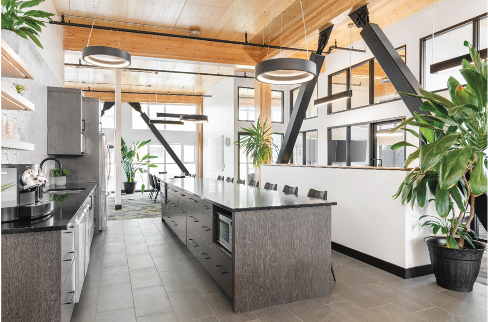
The BRB braces and timber frames resulted in a beautiful, polished architectural finish with a high-performing, buildable, and efficient lateral system. This new hybrid BRB-timber system serves as a great example of thoughtfully combining engineering mechanics, knowledge of the materials, and aesthetics. Meanwhile, the investigation of the SFRS options available exposed the impressive range of possibilities that can be applied to mass timber construction.■
Project Team
EOR: Mehrdad Jahangiri
Project Manager: Ilana Danzig
Design Engineer: Jackson Pelling
Design Engineer: Brendan Fitzgerald
References
Galindo, Oscar, et al. “Supplemental Damping for the seismic retrofit of 8-storey RC Hotel building in the Mexican Pacific using Yielding Restrained Braces – Part A, Comparison of alternatives.” 12th Canadian Conference on Earthquake Engineering, Quebec, QC, 2019
Dong, Wenchen, 2021 “Seismic Performance of Glulam Frames with Buckling Restrained Braces (BRBs)” [Doctoral thesis] University of Canterbury