
Simplifying building design with fluid viscous dampers by using an ICC-approved prescriptive method.
Fluid Viscous Dampers (FVDs), or simply “dampers,” effectively dissipate seismic energy to reduce steel and foundation costs in new buildings and improve structural resilience, especially for critical facilities. A new building design procedure using dampers has been developed, validated, and published with certification from the International Code Council. This new design procedure opens the door for more damper applications in new steel structures by eliminating the requirements for nonlinear response spectrum analysis and peer review in damped buildings.
Introduction to Dampers
The lateral force resisting systems (LFRSs) used as standard practice by structural engineers rely predominately on hysteretic damping to dissipate seismic energy. This means axial deformation of braces, beam sections hinging in moment frames, rebar yielding, and concrete crushing in shear walls. For low-level shaking, the damage incurred can be negligible in most modern buildings. In moderate to large earthquakes, however, the damage can be significant, and while these buildings may meet the code intent of not collapsing, they can be too expensive to repair and result in a total loss. This became clear after the 2010/2011 Canterbury Earthquake Sequence in Christchurch, New Zealand. A study after the earthquakes found that over 65% of the “significant” buildings were demolished after the earthquakes, having lasting effects on the city (Gonzalez, Stephens, Toma, Elwood, & Dowdell, 2021).
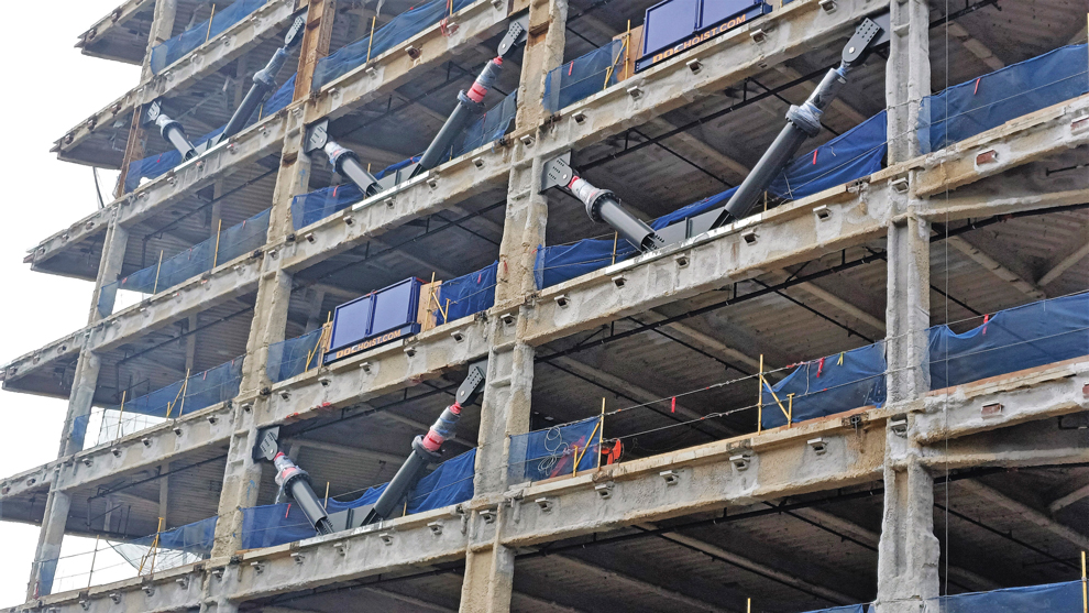
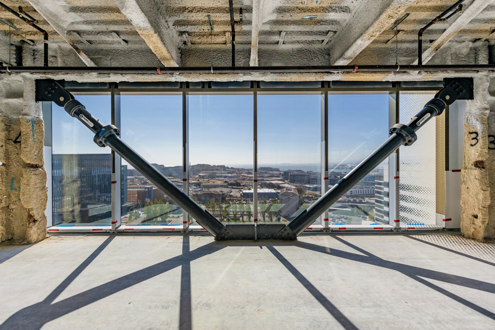
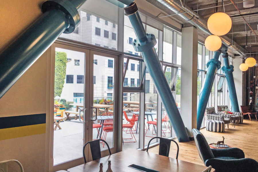
FVDs have been successfully used in buildings for nearly 30 years to dissipate seismic energy, primarily through converting energy to heat rather than yielding structural elements. Typically, dampers are placed within building stories to capitalize on the differential movement between floors (see Figure 1) and are often left exposed after the building is finalized (see Figure 2).


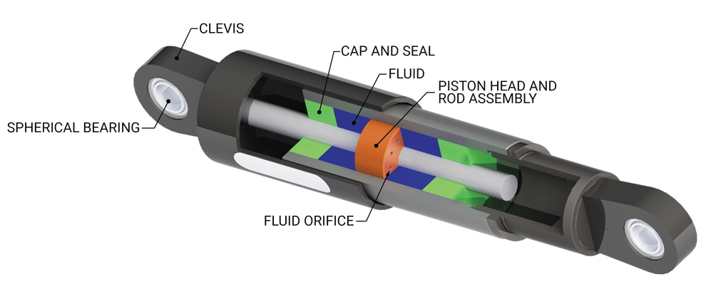
The piston head of a damper contains specialized orifices, where the size, quantity, and shape of these orifices control the damper force-velocity relationship and ultimately impact the amount and efficiency of the energy dissipated (Figure 3).
The fundamental equation that describes the behavior of FVDs is:
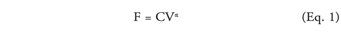
-where F is the output damper force, C is the damping constant, V is the induced velocity, and α is the damping exponent. For seismic applications, an α of 0.4 provides significant energy dissipation but with a lower output force when compared with linear dampers (α equal to 1.0).
FVDs have some unique properties which make them advantageous for building applications:
- Reduce both drift and acceleration: Most LFRSs use increased stiffness to control drift but at the expense of higher floor accelerations. FVDs are unique because they help control inter-story drift while reducing floor accelerations.
- Does not impact building period: FVDs do not introduce stiffness into the structure (they have no displacement-dependent characteristics) and, therefore, do not change the fundamental lateral period of the structure. This means that damped structures can be designed to have longer periods than their undamped counterparts, reducing their seismic response to earthquakes and the structure’s demands.
- Flexibility in placement: Because dampers do not introduce stiffness, they are not bound by the vertical regularity expectations of traditional LFRSs. Therefore, they do not require vertical stacking up the height of a building. Damper locations can shift from floor to floor depending on the functional and aesthetic needs, which often are heavily influenced by architectural preference.
- Out-of-Phase Behavior: FVDs are velocity-dependent devices, which means that their peak force occurs out-of-phase with the displacement-based seismic demands on the LFRS. When the building is at peak displacement, and therefore peak strain and stress in the LFRS, the dampers are experiencing zero velocity and, therefore, are not generating an output force. Conversely, when the building moves through the origin, the strain in the LFRS is zero, whereas the dampers generate their peak force corresponding to the peak velocity.
Damper Applications in Buildings
Currently, most FVD projects in the U.S. are retrofits of Pre-Northridge Steel Moment Frames and Nonductile Concrete Moment Frames in high seismic regions. For retrofits, reducing drifts without stiffening the building helps avoid costly foundation retrofits and can reduce demands on existing elements to within their current capacity.
However, using FVDs in new construction has remained relatively limited to essential facilities like hospitals and emergency centers or applications where resiliency is a key objective. The code-driven requirements for NLRHA and peer review when designing with dampers are a barrier for many projects. To help mitigate these barriers, a new prescriptive method for designing new steel moment frame structures with FVDs was developed by Taylor Devices, trademarked as the Taylor Damped Moment Frame™ (TDMF™).
This special damped moment frame system was developed and validated through the rigorous AC494 and FEMA P-695 processes and is officially approved in the International Code Council Evaluation Services ESR-4769 (https://icc-es.org/report-listing/esr-4769/). This process included the design of over one hundred archetype structures and analyzing each structure’s collapse probability using advanced nonlinear analysis with a suite of 44 horizontal ground motion records. Through this process, it was demonstrated that structures designed in alignment with this design procedure meet the intention of the code, which is to have a less than 10% probability of collapse at an MCE-level seismic event.
The system design procedure utilizes Modal Response Spectrum Analysis (MRSA) for the steel moment frame analysis and design with modifications to ASCE 7 Chapter 12 to account for the positive impact of the dampers. The dampers are omitted from the analysis model and are designed separately through a prescriptive approach.
System Description
The LFRS for the system is the steel special moment frame (SMF), where ordinary and intermediate steel moment frames are not eligible due to a lack of seismic detailing requirements. The FVDs are supplemental to the LFRS. Therefore, they may be placed within the SMF or in so-called gravity frames. The frames that host the FVDs are designated as the Damper Frames (DFs). The SMFs and DFs are procedurally addressed separately, but in cases where the SMF and the DF share common elements (as is the case when the dampers are within the SMF), there is an iterative step where the damper force is introduced as a static demand back into the SMF. It should be noted that when the FVDs are within a gravity frame, the beam-column connections do not have to be modified; they can remain as traditional gravity frame connections (see ESR-4769 for more detail).
Other system limitations include:
- Flexible floor diaphragms as defined by ASCE 7 §12.3.1.1 or §12.3.1.3 are not permitted.
- Buildings must not have horizontal irregularity Type 1b, extreme torsional irregularity, as defined in ASCE 7 Table 12.3-1.
- A building height limit of 300 feet (measured from the base to the highest floor).
- At least two dampers must be installed in both principal directions on every floor for a minimum of four dampers per floor. The dampers must be arranged with at least one damper on either side of the center of stiffness. While asymmetry in the damper placement is permitted, any damper-induced torsion must be accounted for through modification of the accidental torsion consideration (ASCE 7 § 12.8.4.2).
- Taylor Devices, Inc. must provide the dampers.
While the LFRS must be SMFs, there are no limitations on the rest of the structure so long as it meets the requirements above. This means that the system is permissible with steel-framed buildings. Still, it can also be applied with mass timber, concrete, or masonry structures with an SMF lateral system and semi-rigid or rigid diaphragms. Notably, the ICC-approved system and prescriptive procedure do not apply to existing buildings.
Moment Frame Design
The SMF is designed per AISC 341, 358, and 360 with demands from a modified MRSA. The system procedure is compatible with any pre-qualified or approved proprietary moment frame system.
The key design parameters and modifications to ASCE 7 Chapter 12 are:
R = 8, Ω0 = 3 (unchanged from Table 12.2-1)
Cd = 4.5 (instead of 5.5 from Table 12.2-1)
Scaling of forces: MRSA base shear is scaled to 75% of the ELF base shear, as opposed to 100% (modification to ASCE 7 § 12.9.1.4.1)
Scaling of drifts: When scaling MRSA drifts in accordance with ASCE 7 § 12.9.1.4.2, the factor CS used in Equation 12.8-6 is replaced with CS,d calculated as:
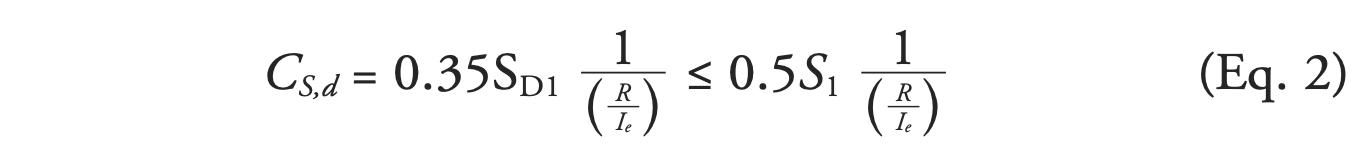
There is a 25% reduction in seismic base shear for force-controlled frames. Whereas for drift-controlled frames, there is an 18% reduction in floor displacements and a reduced minimum when Equation 12.8-6 from ASCE 7 controls. In both cases, the reduction in response leads to softer SMFs compared to undamped frames. Therefore, with longer periods and further down on the response spectrum, seismic demands are even further reduced.
Damper Frame Design
The DF consists of the FVDs, extender braces, connections, gusset plates, beams, columns, diaphragms, and foundations that form the damper force load path. Selection of the damper properties, C and α from Equation 1, comes from a prescriptive approach that occurs outside the MRSA used to design the SMFs. The damping exponent, α, is fixed at 0.4 for this system. The damping constant, C, is calculated using stiffness proportional damping up the structure’s height through the following series of equations.
First, a target linear damping constant, Cji(L), is calculated.
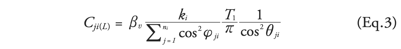
-where,
βv = Target Viscous Damping Ratio = 0.25
θji = angle of inclination of the jth damper on the ith story measured from the horizontal
φji = angle of the DF containing the jth damper on the ith story measured from the principal direction (zero degrees when the DF aligns with the principal direction)
T1 = fundamental translational elastic period in the principal direction of interest
ki = the ith story linear stiffness in the principal direction of interest
ni = total quantity of dampers being considered in the principal direction of interest at the ith story
If all the DFs are aligned along the principal directions, the terms ∑j=1nicos2 φji simplifies to ni. Equation 3 will produce a design where all the dampers on the ith floor in the principal direction of interest will have the same damping constant. For example, there are cases where varying damping constants are useful to balance an asymmetric damper placement. For this purpose, an alternative formulation of Equation 3 is provided in ESR-4769 which accounts for the summative damping, thereby allowing for varied damping constants on the same floor for a given principal direction.
The linear damping constant is translated to a nonlinear damping constant, Cji(NL), via equivalent energy dissipation at the peak pseudo-velocity. Individual damper displacements from the MRSA determine a pseudo-velocity for each device. At a preliminary analysis stage, the average MRSA drift could be used.
The pseudo-velocity is calculated as:
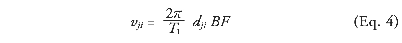
-where,
dji = displacement (stroke) of the jth damper on the ith story measured from the MRSA analysis
BF = base shear correction factor, which removes the effects of the base shear scaling from the DE level damper displacement = min (1.0, Vt /(CS,dW)
Vt = modal base shear from ASCE 7 Section 12.9.1.4.2
W = seismic weight of the full structure
The nonlinear damping constant is then calculated as:

-where
λ = 3.582 for velocity [in./sec] and α equal to 0.4
The specified nonlinear damping constant, Cji(NL)spec, must be within a range of minus 10% and plus 30% of the values calculated by Equation 5, giving the designer flexibility and often allowing for smoothing of the damper designs over several floors.
The damper force and required stroke are then calculated to guide the engineer in selecting the damper size. The damper force at the DE level is determined based on Equation 1, except that the pseudo-velocity calculated in Equation 4 is modified to account for higher mode effects and nonlinearity. The DE level damper force is amplified to MCE level forces (×1.18) to correspond to the damper force ratings and by an overstrength factor (×1.66) to design the DF components.
The damper stroke is also determined with an “overstrength” factor, whereby the damper strokes determined from the MRSA are amplified by the importance factor, Ie, and a factor dependent upon the building’s Seismic Design Category and the number of stories. This amplification factor ranges from 2.5 to 3.5, reducing the dampers’ possibility of exhausting their provided stroke.
Additional requirements not covered here but provided in ESR-4769 account for a minimum extender stiffness, orthogonal damper effects, combined load effects between the lateral system and damper force, and torsional impacts of asymmetric damper placement.
Improved Performance and Resiliency with the System
While the system was developed primarily to produce code-compliant buildings, namely structures that meet the collapse risk intention of the code, the use of dampers inherently improves performance and resiliency over traditional undamped counterparts. Dampers attenuate both story drifts and floor accelerations, reducing damage to structural and nonstructural components. This ultimately leads to less financial losses and building downtime following a seismic event.
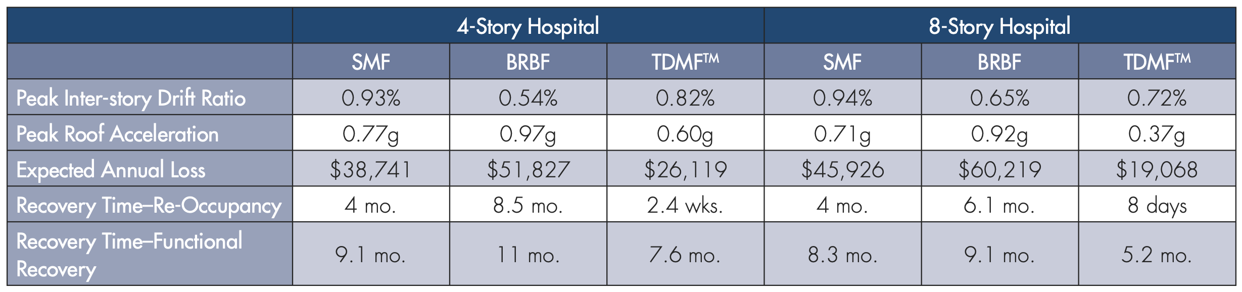
Six archetypical hospital structures were designed to compare the resiliency of the system: 4- and 8- story buildings with LFRS of SMFs, BRBFs, and the system. These buildings were designed by a California structural engineering firm commissioned by Taylor Devices. FEMA P-58 and ATC-138 methodologies were employed to study resiliency using the software platform SP3 developed by the Haselton Baker Risk Group. Table 1 provides the results summary of each building’s performance, loss, and recovery time at the DE level.
These results demonstrate the system’s ability to, out of the box, contribute significantly to improving building resiliency. Floor accelerations and expected mean annual losses are significantly reduced. Time to achieve re-occupancy, a crucial criterion for any hospital, shifts from months to days. Further, the changes needed to make the system achieve immediate occupancy or higher resiliency standards are minor compared to the other systems and rest largely on decisions outside the lateral system. The dampers are designed to maintain their full function even after experiencing an MCE-level seismic event and do not require replacement or servicing.
With our industry increasingly acknowledging the reality of our code minimum building performance, the system will become a critical tool in the toolbox to provide code-level buildings that increase our community resiliency. The system design procedure opens the door for more applications of dampers in new steel structures, removing barriers of NLRHA and peer review, which add cost and time to any project. Additionally, removing NLRHA increases the accessibility of dampers to many engineering firms that might otherwise not have considered a damped design. This new system prescriptive design approach can be a key component in the structural engineering community’s efforts to improve public safety by providing facilities that do more than just survive earthquakes without collapsing – we can help make our cities resilient to avoid the post-earthquake losses seen elsewhere.■
References
Gonzalez, R. E., Stephens, M. T., Toma, C., Elwood, K. J., & Dowdell, D. (2021). Post-earthquake Demolition in Christchurch, New Zealand: A Case-Study Towards Incorporating Environmental Impacts in Demolition Decisions. In S. Akkar, A. Ilki, C. Goksu, & M. Erdik (Eds.), Advances in Assessment and Modeling of Earthquake Loss. Springer, Cham. doi:https://doi.org/10.1007/978-3-030-68813-4_3