
Recognize how and where building enclosures must accommodate differential shrinkage in wood-framed buildings.
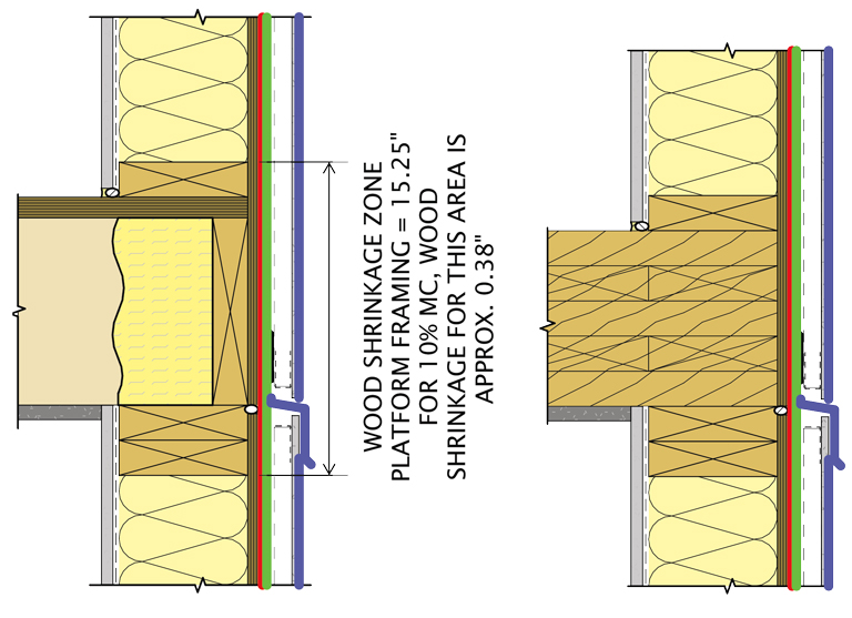
Dimensional change in wood, often called wood shrinkage, is an important consideration for wood-frame multi-story buildings. The decrease in moisture content (MC) of wood from construction-stage to in-service conditions can be over 10%, resulting in wood shrinkage at a rate of approximately 0.25% change in dimension per 1% moisture change. Wood shrinkage must be accommodated where there is differential movement between the wood structure and building components, such as cladding, fenestrations, MEP equipment, or interfaces with masonry structures. Cladding elements not accommodating wood shrinkage can experience cracking, spalling, buckling, or reverse slope issues.
Background
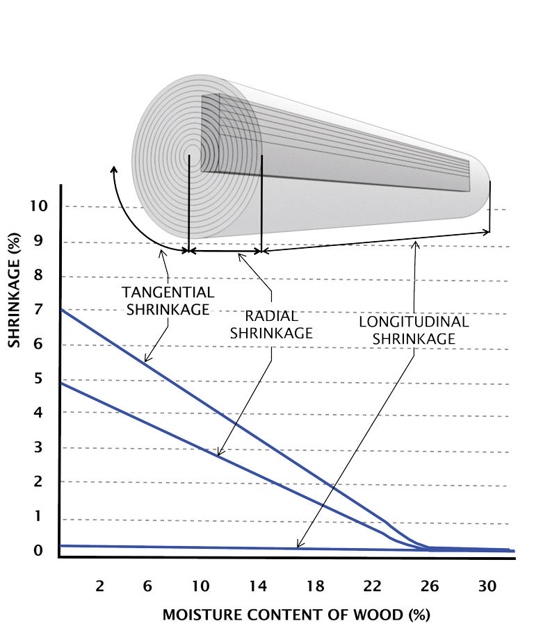
The magnitude of dimensional change in wood varies depending on the grain orientation, wood species, and change in MC. Since wood is an anisotropic material with different properties in tangential, radial, and longitudinal directions, knowing the grain orientation of the wood is essential. Wood shrinkage is most significant in the tangential and radial directions while usually negligible (less than 0.2% [Rowell 2005] in the longitudinal direction, as shown in Figure 1). Therefore, a designer should assume tangential orientation as a conservative approach when calculating wood shrinkage unless more specific information is available. Thus, most shrinkage in wood-frame buildings occurs at floor lines where rim joists and sill plates are installed with tangential and radial grain directions aligned with the height of the building.
Wood is also a hygroscopic material, readily absorbing moisture from the air or bulk water, which causes the wood to expand. When the moisture exposure decreases, the wood dries out and shrinks until the MC has reached equilibrium with the surrounding conditions. This cycle will continue for wood exposed to changing temperatures and relative humidity. For enclosed structures, the MC of wood framing is typically greater during construction when exposed to exterior conditions. When the building is closed-in, the MC decreases until it reaches relatively consistent indoor conditions, resulting in a final equilibrium state with minimal dimensional change. The 2021 International Building Code specifies that preservative-treated wood shall not be enclosed when the framing members exceed 19% MC to minimize the risk of biological growth and, at the same time, limit the amount of wood shrinkage by limiting the MC differential between construction and in-service framing. Wood framing may have an MC above 19% due to wet storage conditions, from wetting during transit to rain events.
A building’s structural design can greatly reduce the use of members that may contribute to wood shrinkage, such as by using balloon-framed walls rather than platform walls or engineered lumber. However, some wood shrinkage is expected for light-frame and mass timber construction.
Mass timber
Mass timber, such as cross-laminated timber (CLT) panels and glulam beams, have similar dimensional stability as dimensional lumber concerning changes in MC. However, it is likely to experience less shrinkage. This is due to the lower initial MC of the wood, which must be below 15% for the laminating process and is typically around 12%. Kiln-dried dimensional lumber is targeted to an average MC of 15%, at most 19%. The lower MC of mass timber is closer to the equilibrium MC of wood in interior spaces, which typically averages around 6 – 12% [Simpson 1999]. In addition, mass timber is less susceptible to MC increases and related dimensional changes from isolated, short-term wetting events due to the thicknesses of the members. The relationship between MC and the depth of wood is exponential from the outer plies to the inner core of mass timber. For example, in a recent six-story mass timber project, the wood shrinkage across the 5- to 7-ply CLT floors was determined to be 3/16-inch over a combined total of approximately 51 inches of CLT depth with a 10% MC difference between the construction and closed-in conditions (measured in the outer plies). Compare this to the expected wood shrinkage in dimensional lumber, which is calculated to be approximately 2 inches in a similar building with platform-framed construction with dimensional lumber.
Building Enclosure Design Goals
The building enclosure is what separates conditioned spaces from unconditioned or exterior spaces. It consists of the air, water, vapor, and thermal control layers and relies on the continuity of these layers to keep the building warm and dry (Figure 2). Part of an effective enclosure design allows movement of the structure while maintaining continuity across these control layers.
Several common building conditions exist where wood shrinkage can cause failures in the building enclosure, including:
- Cladding across platform-framed floor lines
- Cladding with expansive properties
- Concrete or masonry interfaces, such as zero-lot line interfaces or concrete core
- Externally supported balconies
Cladding Across Platform-Framed Floor Lines
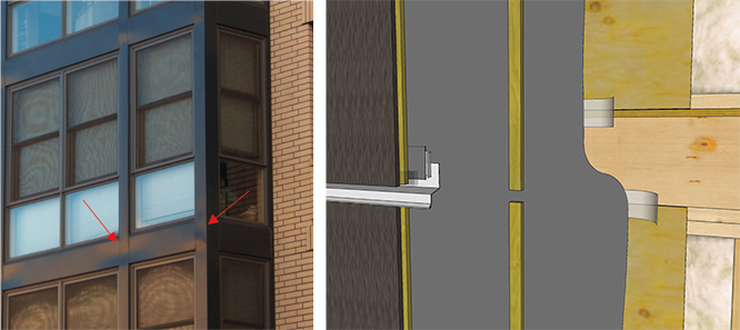
Cladding across mass timber or traditional platform-framed floor lines is subject to wood shrinkage. It’s typical to have a gap in the sheathing at these locations for sheathing expansion during construction, which must translate through the air/water barrier and cladding. Figure 3 shows a wood-framed building with metal cladding spanning across platform wood-framed floors, which caused buckling of the cladding at floor lines. Through-wall flashing is the preferred detail to accommodate wood shrinkage at floor lines, as shown in Figure 3. This approach allows for wood shrinkage. It also provides through-wall drainage at each floor line to prevent water accumulation behind cladding over several stories, which can cause issues, particularly with cement plaster systems. Other options include overlaps or gaps in cladding and utilizing a UV-stable air/water barrier at gaps.
Differential Shrinkage of Cladding
Differential shrinkage occurs when you have two materials that are interfacing but do not exhibit similar behavior when subjected to different moisture or temperature conditions, such as masonry cladding over a wood-frame building. The wood-frame assembly typically experiences shrinkage after the building is closed as the wood dries, while the masonry often does not shrink. Clay masonry is the most problematic because it expands when it absorbs air or bulk water moisture. Therefore, it can compound the wood shrinkage disparity. Other materials, such as concrete masonry unit (CMU)/mortar and concrete, do not expand when exposed to moisture and experience shrinkage due to drying and other mechanisms after pouring.
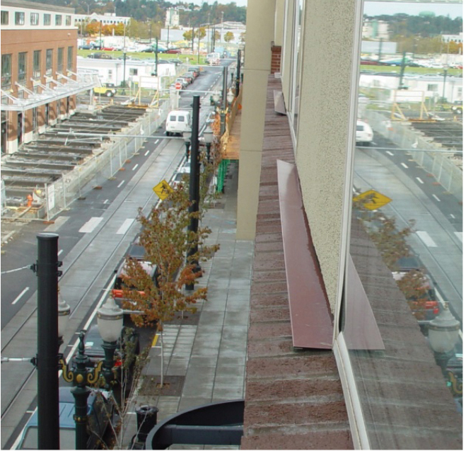
When flashings and interfaces do not accommodate this displacement between the materials, it can result in cladding cracking, spalling, buckling, or reverse slope on flashings. Figure 4 shows a 3-story, wood-frame building with brick and stucco cladding. The brick is bearing on the reinforced concrete foundation, and the stucco is attached to the wood framing above the brick. Wood shrinkage and clay brick expansion led to back-sloped flashing. Other details on this project where wood shrinkage led to deficiencies include window sill flashings and where brick wall cladding interfaced with soffit conditions.
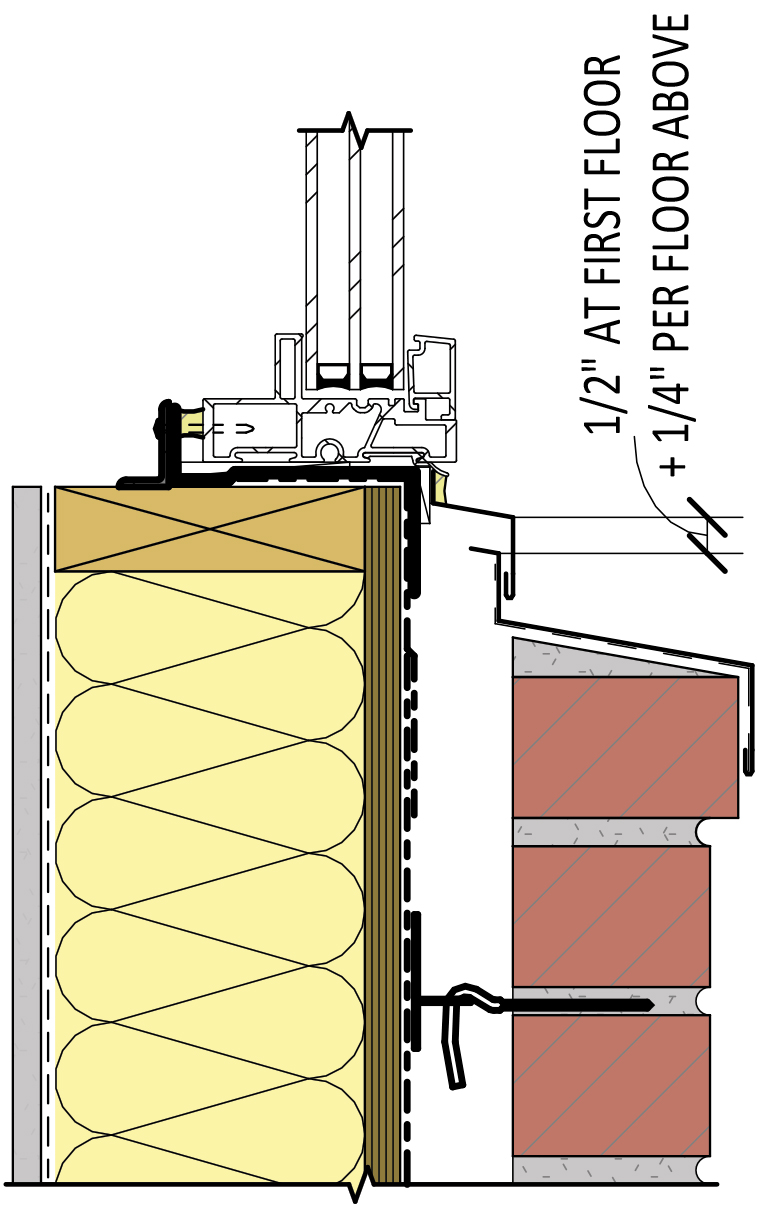
Allowing for wood shrinkage at cladding interfaces can be accomplished with a properly sized sealant joint or overlapping metal flashing (Figure 5). The flashing overlap or sealant joints’ size may differ for each floor based on the anticipated magnitude of wood shrinkage. The sealant joints for this project ranged from 1/2-inch wide on the first floor to 1-1/4-inch wide on the 4th floor, approximately three times the anticipated movement.
Concrete and Masonry Interfaces
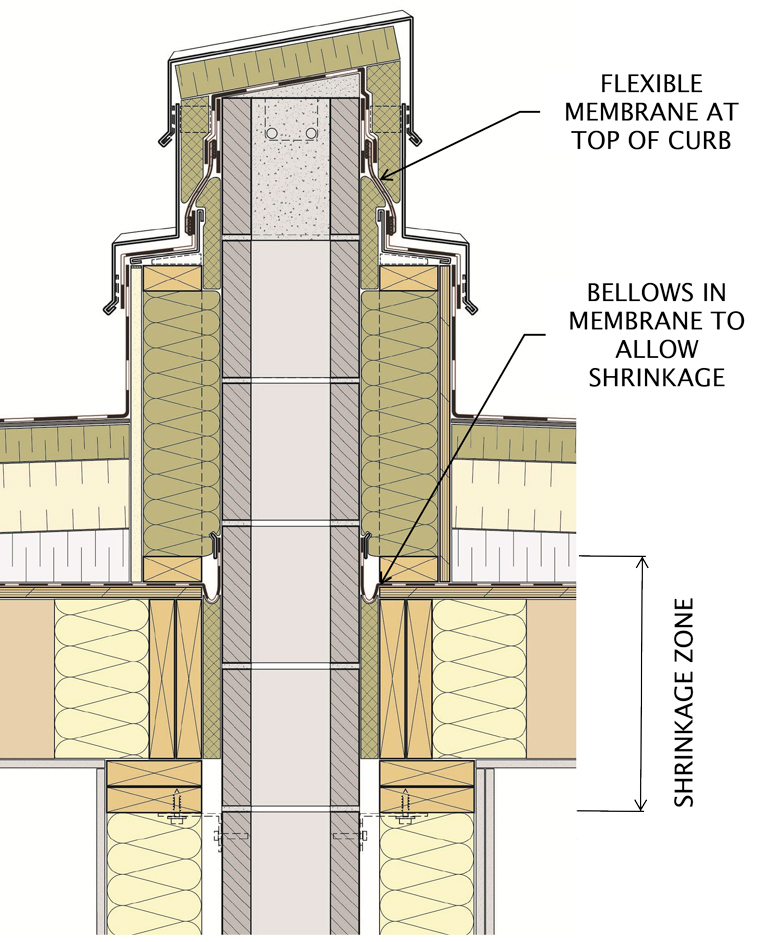
Differential movement is not limited to cladding materials. While CMU and concrete don’t expand like clay brick masonry, the shrinkage of masonry does not match that of wood. Therefore, this must be considered for areas such as elevator core walls, fire walls, and zero-lot-line walls. A similar approach that may include lapped flashing or sealant joints can be used in these areas. At parapet or rooftop interfaces, shrinkage of the entire structure below must be considered at the air barrier, water barrier, and water-shedding surface (metal flashing). This is accomplished by providing bellows in the air-barrier membrane, flexible water barrier sheet membrane, and lapped metal flashing as the water-shedding surface (Figure 6).
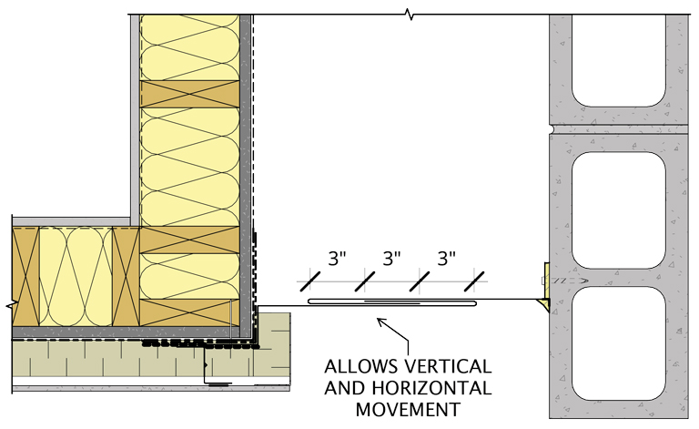
At zero-lot-line wall interfaces where new wood-framed buildings interface with existing structures, including masonry, steel, or closed-in wood-frame buildings, movement can be accommodated with flexible joint material, such as silicone sheet or with metal flashing with sliding joints (Figure 7).
Externally Supported Balconies
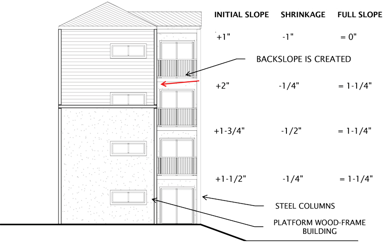
Balconies that are externally supported must match the shrinkage characteristics of the building or increase the initial slope of the walking surface to avoid backslope, as shown in Figure 8. Other options for avoiding this condition include using bolt-on balconies, matching the balcony construction with that of the building, increasing the initial slope of the building to account for differential shrinkage, or using cantilevered balconies that are independently attached on each floor.
From a building enclosure perspective, bolt-on balconies are ideal since this approach simplifies detailing, eliminates saddle conditions, and reduces tie-in interfaces where detailing deficiencies are common. It also increases building performance by allowing air, water, and thermal barrier continuity at the wall-to-balcony interface.
Conclusion
Accommodating wood shrinkage in the building enclosure starts with identifying interfaces where wood shrinkage will cause movement using strategies discussed, such as including properly sized sealant joints, lapped metal flashing, bellows in the air and water barrier membranes, using elastic membranes or providing additional slope in flashings or balconies. ■
References
Rowell, Roger M., Handbook of Wood Chemistry and Wood Composites, 2005, USDA, Forest Service, Forest Products Laboratory, and Biological Systems Engineering Department, University of Wisconsin, Madison, WI.
Simpson, William T., Wood Handbook, Chapter 12 Drying and Control of Moisture Content and Dimensional Changes, 1999, USFS USDA.