
Presentation of an already implemented in practice cross sections of beams with a non-standard shape.
This article discusses the design of custom beams for the support of traveling cranes and is based on twenty years of experience by the author in designing steel structures and presents proven solutions related to the design of beams for traveling cranes. These crane beams are useful for cranes with lifting capacities from two to thirty tons.
The current EN 1993-6 Standard, Eurocode 3 – Design of Steel Structures – Part 6: Crane Supporting Structures, suggests checking the crane beam using two different models. The first model is a full section subject to bi-directional bending and torsion. The second model is an equivalent section subject to bi-directional bending only. This article is limited to the first model only as it is more authoritative and because it more accurately reflects the operation of the crane beam.
Each stage of the crane beam design exercises discussed herein, from manufacturing in the workshop to final assembly, was supervised by the author. This provided an opportunity to fully verify the design solutions used.
Designing the cross-section of a crane beam for cranes with a lifting capacity of 10 to 30 tons
The most common cross-sectional shapes of crane beams are shown in Figure 1. The H steel beam types (HEA/HEB profiles) are wide flange profiles, which according to American standards, are H profiles. Figure 1 shows the most common cross-section. To ensure its greater resistance to torsional buckling and bending in relation to the weaker axis Z it must have wide and thick flanges.
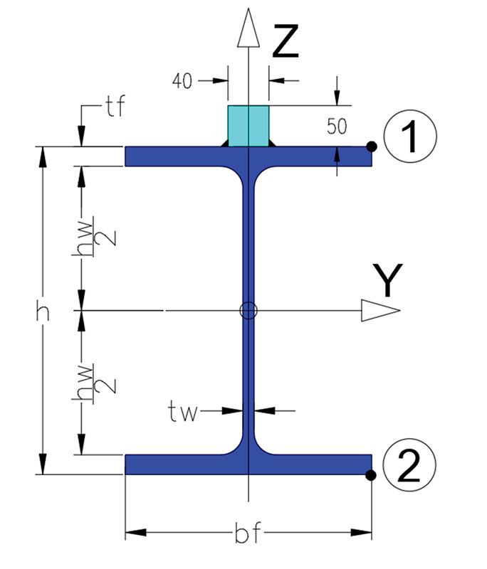
Creating a crane beam from such a cross-section is very simple. Namely, holes are first drilled into the beam’s bottom flanges so that the beams can connect to the column support brackets. Then, the face plates are welded to these beams resulting in finished crane beams. Unfortunately, despite their wide flanges, it is often necessary to reinforce them in the horizontal direction to control deflection and bending in the horizontal plane. Then, more developed cross-sections should be used according to Figure 2, which eventually turn out to be lighter than the most common cross-section shown in Figure 1.

Welding channels or angles improve the section’s resistance in the horizontal direction. It is difficult to construct properly because when wings (angles or channels) are welded to the beam, the welding stresses may cause deformation of the wings. To ensure that the channels or angles do not deform after welding, it is recommended to use fins to maintain the shape of the section. This, of course, is labor intensive and increases cost. If it is acceptable to the structural engineer, fins can be welded to the web only and not to the bottom of the top flange of the beam.

An alternative to the sections with “wings,” angles with unequal legs can be welded to the bottom of the beam’s top flanges, as shown in Figure 3. This forms a double box at the compression flange, which significantly improves the section’s torsional characteristics and increases the lateral buckling resistance. Figure 3 shows the fillet welding of angle sections to I-sections. It is always possible to choose a suitable angle with unequal legs with a selected I-beam profile. The angle is connected to the I-beam by fillet welds, as shown in Figure 3.
The example calculation helps to demonstrate the advantages of the above solution. The analysis was carried out for Eurocode 3 Load Combination Group 5 (crane passage), which is a group of reactions from the crane during its passage with full load when the load is in the most unfavorable position. In addition, in this situation, a lateral force is introduced, which is the result of crane bridge skews. The passage of the crane along a curved, not straight, track, see Figure 6.

Example Calculation #1
Assumptions:
- Overhead crane with a lifting capacity of 25 tons
- Single-span beam
- V = 190 kN [42.7 Kip] (maximum load from 1 crane wheel)
- HT = 24 kN [5.39 Kip] (bevel force of the crane bridge)
- a = 3.0 m [3.28 yd] (crane wheel spacing)
- L = 7.5 m [8.2 yd] (span of the freely supported beam)
- Steel: S235 (equivalent to A570 Gr. 36 in USA), rail – 40 × 50 [1.57 × 1.96 in] bar square section welded directly to the top flange of the beam.
- Internal forces: My,Ed = 635 kNm [155 Kipyd], Mz,Ed = 58 kNm [14.16 Kipyd] For determination of these internal forces, see Figure 4.

Five different cross-sections were analyzed:
- Section 01 – HEB 550
- Section 02 – HEA 550 + wings with L65 × 65 × 9
- Section 03 – welded plate girder [top chord Bl. 400 × 30, web Bl. 15 × 440, bottom chord Bl.300 × 30]
- Section 04 – HEA 550 + 2 × Bl.25 × 100 – (This cross-section is shown on the Figure 5)
- Section 05 – HEA 550 (+ 2 L150 × 75 × 9)

Profile dimensions:
- HEA 550 h=540 mm [21.25 in], bf= 300 mm [11,8 in], tw = 12.5 mm, tf = 24 mm
- HEB 550 h=550 mm [21.25 in], bf = 300 mm [11,8 in], tw = 15.0 mm, tf = 29 mm
Vertical and horizontal deflection criteria:
- dV < L/600 = 7500 / 600 = 12.5 mm [0,5 in]
- dH < L/600 = 7500 / 600 = 12.5 mm [0,5 in]
The calculation results are summarized in Table 1.

Conclusions – Example #1
Only Section 05 meets all the conditions. The stress in the tension flange does not exceed < fy = 235 MPa (Point 2 of the cross-section) and the load-bearing capacity with stability (see calculations below) is also not exceeded (Point 1 of the cross-section). Section 05 has a torsional moment of inertia more than seven times greater than the average torsional moment of inertia of Sections 01 to 04. This results in strains from deplaning (see Figure 7) due to torsion being approximately two times lower than the other sections. This also affects the critical moment of lateral buckling, which is more than 1.5 to 2 times greater than other sections. Therefore, the reduction in carrying capacity due to overall stability (here lateral buckling) is small.

In Row No. 4 of Table 1, a check of the so-called “wide flange effect” according to [2] is included. Only Sections 01 and 05 do not require a reduction in flange width. The analysis omits the flange reductions for Sections 02, 03 and 04, as these sections do not meet the load-bearing conditions and the load-bearing violations would be even greater.
Please note, Section 05 is one of the lightest sections making it an economical and efficient steel section choice. Section 05 is also very compact. The total width does not exceed the width of the beam flanges. As a result, the support bracket widths for the crane beams can be shorter which will reduce the column’s bending moment.
Figures 8 through 9 show crane beam Section 05 located in the paint shop hall of the PROMUS Katowice company where there are two cranes with a lifting capacity of 5 tons each, operating on a track.
Load-bearing capacity with stability is described by the following formula

Where:
My,Ed; Mz,Ed – Maximum bending moments of a beam cross-section with respect to its axis Y-Y i Z-Z
Bx,Ed – Maximum bi-moment acting on the beam, resulting from restrained torsion
𝛘w = – Torsional buckling coefficient.
My,Rk = Wy fy – Bending capacity of the cross-section with respect to its axis Y-Y
Mz,Rk = Wz fy – Bending capacity of the cross-section with respect to its axis. Z-Z
Bx,Rk = W𝜔 fy – Bi moment capacity of the cross-section.
𝛄M1— – Material safety factor = 1.0 or 1.1


Designing the cross-section of a crane beam for cranes with a lifting capacity of 2 to 10 tons
For lightweight crane beams, hot-rolled IPE sections are the most common base profile. According to American standards, these are W profiles. To improve their deflection and bending resistance in the horizontal direction, wings created by welded angles [similar to wide-flange I-beam sections] (see Figure 11) or channels are used (usually the largest available from wholesalers are C300, see Figure 10.

Figure 11 shows additional stiffeners that prevent deformation of the “wings” after welding.

An alternative to the above sections is to combine the IPE profile with “blanks” cut from 250x100x8 rectangular pipe (RP) and welded to an IPE 450 I-beam (flange width 190 mm [7,48 in]), see Figure 12.

The relationship is as follows: (designations as in Figure 13)

a =~ [f − (bf − tw) /2 ] / 2, a = [250 − (190 − 9) / 2 ] /2 = ~80 mm [3,15 in], hence total section width b = 190 + 2 × 80 = 350 mm [13,8 in]
Also, instead of a “blank”, it is possible to use bent sheet metal (8 to 12 mm thick [0,31-0,47 in]). (See Figure 13) In order to optimize the reinforcement effect in the horizontal direction, it is recommended that the following relationship is fulfilled: Bmin > 1.3 × A.
An example calculation was prepared to illustrate the advantages of the above cross-section. The analysis was carried out for Eurocode 3 Load Combination Group 5 [crane passage] as in Example #1.
Assumptions:
- Overhead crane with a lifting capacity of 8 tons
- Single-span beam.
- V = 75 kN [16.8 Kip](maximum pressure of 1 crane wheel)
- HT = 15 kN [3.35 Kip](bevel force of the crane bridge)
- a= 3.0 m [3.28 yd] (crane wheel spacing) and L = 7.5 m [8.2 yd](span of the freely supported beam
- Steel: S235 (equivalent to A570 Gr. 36 in USA), rail – 40 × 50 [1.57 × 1.96 in] bar square section welded directly to the beam top flange.
- Internal forces: My,Ed = 257 kNm [62.7 Kipyd], Mz,Ed = 36 kNm [8.8 Kipyd] based on [1].
Four different cross-sections were analyzed:
- Section 06 – IPE 450 + U300
- Section 07- IPE 450 + wings with L75 × 75 × 10
- Section 08 – HEA 400
- Section 09 – IPE 450 + RP 250 × 100 × 10
Profiles dimensions:
- HEA 400 h=390 mm [15.35 in], bf = 300 mm [11,8 in], tw = 11 mm, tf = 19 mm
- IPE 450 h=450 mm [17.7 in], bf = 190 mm [7,48 in], tw = 9,4 mm, tf = 14,6mm
- C 300 h = 300 mm [11.8 in], bf = 100 mm [3,94 in], tw = 10 mm, tf = 16 mm
Vertical and horizontal deflection criteria:
- dy < L/600 = 7500 / 600 = 12.5 mm [0,5 in]
- dH < L/600 = 7500 / 600 = 12.5 mm [0,5 in]
- The calculation results are summarized in Table 2.

Conclusions – Example #2
Only cross-section 09 meets all the conditions. The stresses in the tension flange are not exceeded < fy = 235 MPa (Point 2 of the cross-section) and the load-bearing capacity with stability (Point 1 of the cross-section) is also not exceeded. Section 09 has a torsional moment of inertia more than 25 times greater than the average torsional moment of inertia of Sections 06 to 08. This results in strains from deplaning (see Figure 7) due to torsion being approximately four times lower than the other sections. This also affects the critical moment of torsion, which is more than four times greater than the other sections. Therefore, the reduction in carrying capacity due to overall stability (here lateral buckling) is small.
Row 4 in Table 2 includes a check of the so-called “wide flange effect.” A 13% violation causes virtually no flange reduction.
Please note, Section 09 is one of the lightest sections making it an economical and efficient steel section choice.
Final conclusions
The I-section, reinforced in such a way that two “boxes” are formed at the compression flange, is an economical and efficient steel section that provides excellent strength and stiffness resistance. It is recommended for use at crane beams, overhead cranes and suspended cranes and hoists.
In hall spaces with cranes, the spacing of the load bearing system determines the span of the crane beam. By using the proposed beam cross-sections, the spacing can be more efficient if the load bearing system can be spaced every 7 to 7.5 m instead of the standard 6 m spacing.
The calculation of the cross-sectional indices (basic and sectional) was performed in Autodesk Robot Structural Analysis 2014. Critical moments of lateral buckling and cross-sectional indices were calculated in Idea StatiCa Beam 10.1■
References
Portions of this article were published as “Nowatorskie rozwiązania belek podsuwnicowych” in the magazine Inżynieria I Budownictwo (August 2022).
EN 1991-3 (2006) (English): Eurocode 1: Actions on structures – Part 3: Actions induced by cranes and machinery
EN 1993-1-1 (2005) (English): Eurocode 3: Design of steel structures – Part 1-1: General rules and rules for buildings
EN 1993-6 (2007) (English): Eurocode 3: Design of steel structures – Part 6: Crane supporting structures
Żmuda, J. (2022). Konstrukcje wsporcze dźwignic. Wydawnictwo Naukowe PWN
Kurzawa, Z. (2010). Stalowe konstrukcje prętowe obciążone statycznie i dynamicznie. Wydawnictwo Politechniki Poznańskiej.
Rykaluk, K. (2001). Konstrukcje stalowe. Podstawy i elementy. Dolnośląskie Wydawnictwo Edukacyjne.